background image


Nnn-0000nn


© Copyright 2017 SecureALL Corporation 

Page 

of 

18


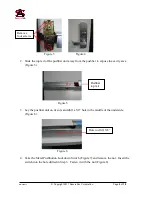
                            Figure 3 


          Figure 4 


2.


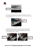
Slide the top rail of the pushbar unit away from the pushbar to expose the cavity area 
(Figure 5). 


                                              Figure 5 
 

3.


Lay the pushbar unit on its side and drill a 5/8” hole in the middle of the underside, 
(Figure 6).


                                             Figure 6 


4.


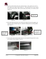
Take the Metal Pushbutton


Lockdown Switch (Figure 7) and remove the nut.  Insert the 

switch into the hole drilled in Step 3.  Fasten it with the nut (Figure 8). 


Hole to drill, 5/8” 

Pushbar 
top rail 

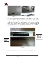
Remove 
four screws 

Содержание SA-PHR

Страница 1: ...rporation All rights reserved under International and Pan American copyright conventions No part of this document may be reproduced in any form or any means electronic or mechanical including photocop...

Страница 2: ...n Date Author Revision Description 1 0 1 3 2014 RAS Initial version 2 0 9 27 2014 RAS Text modified for UL approval 3 0 1 16 2015 RAS New design for full 3 hour fire rating 4 0 2 11 2015 RAS Add optio...

Страница 3: ...pyright 2017 SecureALL Corporation Page 3 of 18 Table of Contents Revision History 2 Table of Contents 3 Introduction 4 Check the Materials 4 Installation Steps 4 Appendix A Panic Hardware Reader Expl...

Страница 4: ...terials needed for installation and that there is no damage to anything from the packing shipping etc If you find any damaged or missing items contact SecureALL immediately for assistance The followin...

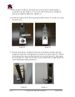
Страница 5: ...se the cavity area Figure 5 Figure 5 3 Lay the pushbar unit on its side and drill a 5 8 hole in the middle of the underside Figure 6 Figure 6 4 Take the Metal Pushbutton Lockdown Switch Figure 7 and r...

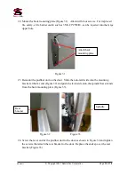
Страница 6: ...rk locations of two screw holes the battery box has 4 holes in the corners pick 2 holes in opposite corners Drill pilot holes using a 40 or 38 bit Orient the battery box inside the rail aligned with t...

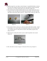
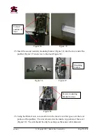
Страница 7: ...e tapped using an M5 screw tap Figure 11 Figure 11 8 A microswitch sensor assembly needs to be installed Figure 12 shows the sensor assembly being placed at an angle on top of the two tapped screw hol...

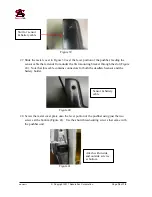
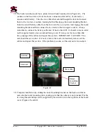
Страница 8: ...w and lock washer Figure 15 Figure 14 Figure 15 10 The cable being held in place by the clip is routed along the side of the pushbar just behind the latch assembly Figure 16 and then fed along the bot...

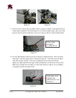
Страница 9: ...e from both the Switch and the cable into a fastener and crimp it using a pair of pliers Figure 21 Repeat for the second set of white wires Figure 20 Figure 21 14 The same procedure is carried out to...

Страница 10: ...e functionality of the latch sensors and the Lockdown Switch Place the cable from Step 17 into the sensor tester as shown in Figure 26 The LED on the left hand side of the board will light As the leve...

Страница 11: ...front lock antenna assembly Figure 27 outside view Figure 28 inside view Figure 27 Figure 28 21 Take the cables that are extending from the front lock antenna assembly and feed it through the central...

Страница 12: ...the pushbar unit on the door Slide the non latch side into the mounting bracket at the far end Figure 32 and push the latch side onto the spindle that extends from the back mounting plate Figure 33 F...

Страница 13: ...7 and screw to the door Figure 38 Figure 36 Figure 37 Figure 38 26 Using the Dremel tool cut a small slot in the metal cover that goes over the lever portion of the pushbar The slot is located on the...

Страница 14: ...hrough the slot Figure 40 Note that this cable contains connectors for both the deadlatch sensor and the battery holder Figure 40 28 Screw the metal cover plate onto the lever portion of the pushbar u...

Страница 15: ...remember to connect the battery cable last Observe the LED It should come on solid red for approximately one second and then go out If it stays on for more than that time unplug all the cables and rep...

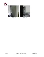
Страница 16: ...Nnn 0000nn Copyright 2017 SecureALL Corporation Page 16 of 18 Figure 43 Figure 44...

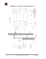
Страница 17: ...Nnn 0000nn Copyright 2017 SecureALL Corporation Page 17 of 18 APPENDIX A INSTALLATION TEMPLATE...

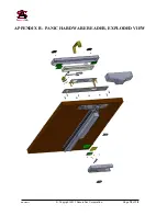
Страница 18: ...Nnn 0000nn Copyright 2017 SecureALL Corporation Page 18 of 18 APPENDIX B PANIC HARDWARE READER EXPLODED VIEW...

Отзывы: