Nnn-0000nn
© Copyright 2017 SecureALL Corporation
Page
10
of
18
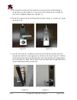
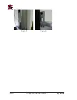
Figure 23 Figure 24
17.
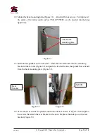
Take the cable in the sensor assembly with the connector and fish it through the bottom
of the bracket installed in Step 16 (Figure 25). The cable should always come out on the
top side when mounted on the door. Use a tie-wrap to secure the cable and the bracket.
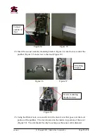
Figure 25
18.
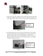
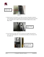
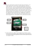
Test the functionality of the latch sensors and the Lockdown Switch. Place the cable
from Step 17 into the sensor tester as shown in Figure 26. The LED on the left hand
side of the board will light. As the lever, deadlatch and Lockdown Switch are
depressed, a different LED will light on the right hand side of the board. If any of the
LEDs does not light, check to make sure all connections are in place. If everything is
as designed, replace the sensor cable.
Figure 26
Cable routing
through the
mounting bracket
LEDs light as lever,
deadlatch and
pushbutton switch are
depressed
Содержание SA-PHR
Страница 16: ...Nnn 0000nn Copyright 2017 SecureALL Corporation Page 16 of 18 Figure 43 Figure 44...
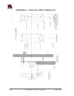
Страница 17: ...Nnn 0000nn Copyright 2017 SecureALL Corporation Page 17 of 18 APPENDIX A INSTALLATION TEMPLATE...
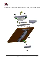
Страница 18: ...Nnn 0000nn Copyright 2017 SecureALL Corporation Page 18 of 18 APPENDIX B PANIC HARDWARE READER EXPLODED VIEW...


