Connecting the logger and installing it on-site
32
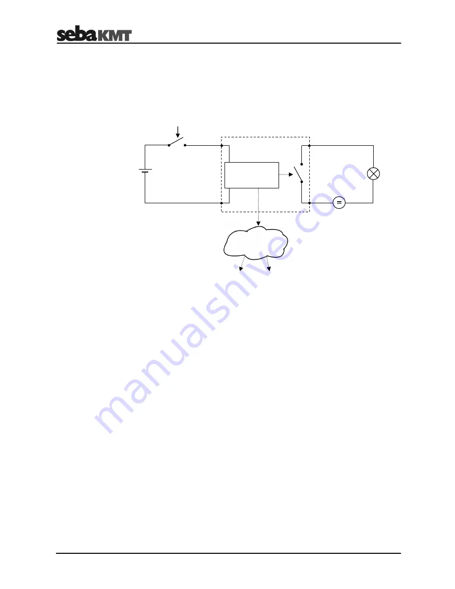
The following example shows an electrical circuit with DC power source connected to
the switching input of the loggers. If an alarm is raised by the alarm device (e.g. light
barrier) is activated, the circuit is closed and the switching input is triggered. Depending
on the alarm configuration, one or two of the internal relays are switched in order to
activate / trigger the load connected to the respective switching output (in this case a
signal lamp) and a SMS and / or e-mail can be sent to predefined receivers.
Alarms can also be triggered when the value of a monitored measurement crosses a
predefined threshold. Please refer to the corresponding section for detailed information
on how to configure the threshold monitoring (see page 58).
Example of an
alarm loop
configured
alarm trigger
Alarm device
GND
Alarm IN
Relay IN
Relay OUT
GSM
SMS
Logger
Содержание Sebalog D-3
Страница 2: ...Consultation with SebaKMT 2...
Страница 8: ...Terms of Warranty 8...
Страница 26: ...Commissioning the logger 26...
Страница 34: ...Connecting the logger and installing it on site 34...
Страница 70: ...Programming the logger using the SebaDataView 3 software 70...
Страница 78: ...Retrieving and evaluating data 78...
Страница 88: ...Changing the battery 88...


