


8
Rev. 3.0 13/06/16
Operation with 1 button radio control:
Using the radio-control with only one key, the following func-
tioning is obtained: the first impulse controls Ascent until it
reaches the end run internal to the motor or until motor time
expires. The second impulse controls the Descent of the fas-
tening; if an impulse occurs before until it reached the internal
motor end run or before motor time expires, the control unit
stops the fastening; a further impulse carries out the motion re-
start in the opposite direction.
Operation with 2 button radio control:
Using the radio control with two buttons, the following operation
is obtained: the first key (“Up” associated with the ascent direc-
tion) controls Ascent until it reaches the internal motor end run
or motor time expires, the second key ( “Down” associated with
the Descent direction ) controls fastening Descent. If during As-
cent the Up control is given again, the control unit continues to
Ascent whereas, while if the Down control is given, the control
unit stops movement.
The same procedure is valid during Descent phase.
Operation with 3 button radio control (BeFree x1):
Using the BeFree x1 radio control, the following operation is
obtained: the ( Up ) key controls ascent until it reaches the in-
ternal motor end run or motor time expires, the ( Stop ) key
controls stopping and the ( Down ) key controls fastening de-
scent. If during ascent or descent a (Stop) control is given, the
control unit stops the fastening. If during ascent or descent a
control is given of the opposite current direction, the control unit
reverses gear.
Operation with 3 keys radio control (BeFree x3 - X6):
Using the BeFree x3 – x6 radio control, the operation previous-
ly described for the BeFree x1 version is obtained. Using the
two side keys ( – ) and ( + ) of the radio control it is also possi-
ble to select controls ( Up - Stop - Down ) for 3 different utilities
(BeFree x3)
or for 6 different utilities (BeFree x6).
Enabling of Sun Sensor with 3 keys radio-control (BeFree
x3 - X6):
The enabling of the Sun Sensor can be carried out as follows:
continuously press for 5 seconds the ( + ) key of a previously
memorised radio-control; the control unit will move Up/Down for
1 second to confirm the occurred enabling of the Sole Sensor.
It is possible to repeat the operation to disable the Sole Sensor
using the same procedure, but by continuously pressing the (-)
key for 5 seconds.
V
ERIFICATION OF THE ROTATION DIRECTION
Attention, after connecting the control unit, Motors, especially if
using with synchronised operation, make sure that the two mo-
tors have the same rotation direction and that, when given an
Ascent command from button or radio control, the control unit
actually completes the Ascent, and the Motors carry out De-
scent if the Descent command is given. If not, restore wire con-
nections of the motor correctly.
G
ROUP OR
M
AIN
C
ENTRALISATION
Centralisation by way of cable using buttons
Centralisation of two or more control units by cable allows sim-
ultaneous Ascent or Descent movement of connected fasten-
ings. Centralisation is carried out by connecting the three input
wires T3 ( Up ), T4 ( Down ) and the common reference “GND
Signal” in parallel.
Centralisation by was of radio using radio control
Centralisation of two or more control units by radio allows sim-
ultaneous Ascent or Descent movement of fastenings.
Centralisation is carried out by inserting equal radio-control
codes (keys) to all control units or by group, at a distance not
higher than 20 metres from the control point, in order to obtain
the total or partial movement of multiple automations. For opti-
mal radio centralisation functioning, it is very important to
choose the place of installation carefully. The field of action is
not only related to technical characteristics of the device, but
also varies based on radio-electric conditions of the area.
O
PERATION OF THE
W
IRELESS
A
NEMOMETER
The electrical control unit will control fastening ascent every
time wind exceeds the intervention threshold selected by the
Wireless Wind sensor.
O
PERATION OF THE
W
IRELESS
S
UN
S
ENSOR
The electrical control unit will control blind Descent after 10
minutes where luminosity exceeds the threshold selected in the
Wireless Sun Sensor. Subsequently, it will control fastening
Ascent after 10 minutes of luminosity under the selected
threshold.
O
PERATION OF THE
W
IRELESS
R
AIN
S
ENSOR
The electronic control unit controls fastening descent as soon
as the sensitive part of the rain sensor is wet from rain.
P
ROGRAMMING
K
EYS AND
I
NDICATOR
LED
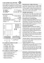
SEL Key
: selects the type of function to memorise, the choice
is indicated by the flashing of the LED. By repeatedly pressing
the key, it is possible to position oneself on the desired func-
tion. The selection remains active for 15 seconds, displayed by
the flashing LED, after which the control unit returns to the orig-
inal status.
SET Key
: carries out the programming of the function chosen
with the SEL key.
Indicator LED
LED on: option memorised.
LED off: option not memorised.
LED flashing: option selected.
---------------------- MAIN MENU -----------------
LED Reference LED Off LED On
1) SYNC MOTORS Independent Motors Synchronised Motors
2) CODE ALL MOT. No code Code TX M1+M2 Pgm.
3) CODE MOT. 1 No code Code TX M1 Pgm.
4) CODE MOT. 2 No code Code TX M2 Pgm.
5) CODE SENS. No code Pgm Sensors Code.
6) WIND SPEED Wind Safety 25 Km/h Pgm. Wind Safety
7)SUN/RAIN INPUT Sun Sensor Rain Sensor
8) SYNC MOTORS
( Motor Synchronisation )
The control unit is supplied by the manufacturer with operation
of Motor 1 and Motor 2 Synchronised with each other, if opera-
tion is required as Motor 1 and Motor 2 independent, proceed
as follows: position the SEL key on the flashing of SYNC
MOTORS LED then press the SET key, the SYNC MOTORS
LED will simultaneously switch off permanently and the pro-
gramming is completed. Repeat the procedure to restore the
previous configuration.
Be careful whenever you change the
operation of this mode, the control unit cancels (Reset) the con-
figurations previously stored.
9) CODE ALL MOT.
( Programming of the radio control for
controlling both MOT.1 and MOT.2 Motors)
Programming of 1 or 2 button radio commands.
The transmission code is programmed in the following manner:
press the SEL key, CODE ALL MOT. LED will start flashing, at
the same time send the first code chosen with the desired radio
control: The CODE ALL MOT. LED will start flashing quickly,
send the second code to be saved, CODE ALL MOT. LED will
remain on and programming will be complete. If the second
code is not sent within 10 seconds the control unit will exit the
programming phase and select the function with only one but-
ton of the radio control. If all available radio controls have been
memorised, by repeating the programming operation, all indica-
tor LEDs will start to flash very fast, with the exception of the
CODE ALL MOT. LED that remains on fixed, indicating that fur-
ther memorising is not possible.


