TROUBLESHOOTING CHART
10
SYMPTOM
POSSIBLE CAUSE(S)
CORRECTIVE ACTION
Motor will not run
1. Disconnect switch is off
1. Be sure switch is on
2. Fuse is blown
2. Replace fuse
3. Starting switch is defective
3. Replace starting switch
4. Wires at motor are loose,
4. Refer to instructions on wiring. Check and tighten all wiring.
disconnected, or wired incorrectly
Capacitor voltage may be hazardous. To discharge
capacitor, hold insulated handle screwdriver BY THE HANDLE
and short capacitor terminals together. Do not touch metal
screwdriver blade or capacitor terminals. If in doubt, consult a
qualified electrician.
Motor runs hot and 1. Motor is wired incorrectly
1. Refer to instructions on wiring
overload kicks off
2. Voltage is too low
2. Check with power company. Install heavier wiring if wire
size is too small (See Electrical, Page 6)
Motor runs but no
*1. Pump in new installation did
1. In new installation:
water is delivered
not pick up prime through:
a. Improper priming
a. Re-prime according to instructions
b. Air leaks
b. Check all connections on suction line
c. Leaking foot valve
c. Replace foot valve
*2. Pump has lost prime through:
2. In installation already in use:
a. Air leaks
a. Check all connections on suction line and shaft seal
b. Water level below suction
b. Lower suction line into water and re-prime. If receding water level
of pump
in well exceeds suction lift, a deep well pump is needed
3. Impeller is plugged
3. Clean impeller; see Maintenance
4. Check valve or foot valve is stuck
4. Replace check valve or foot valve
in closed position
5. Pipes are frozen
5. Thaw pipes. Bury pipes below frost line. Heat pit or pump house.
6. Foot valve and/or strainer are
6. Raise foot valve and/or strainer above well bottom
buried in sand or mud
Pump does not
1. Water level in well is lower than
1. A deep well jet pump may be needed (over 20 ft. to water)
deliver water to full
estimated
capacity (Also
2. Steel piping (if used) is corroded or
2. Replace with plastic pipe where possible, otherwise with new
check point 3
limed, causing excess friction
steel pipe
immediately above)
3. Offset piping is too small in size
3. Use larger offset piping
*(Note: Check
prime before look-
ing for other
causes. Unscrew
priming plug and
see if there is
water in priming
hole.)
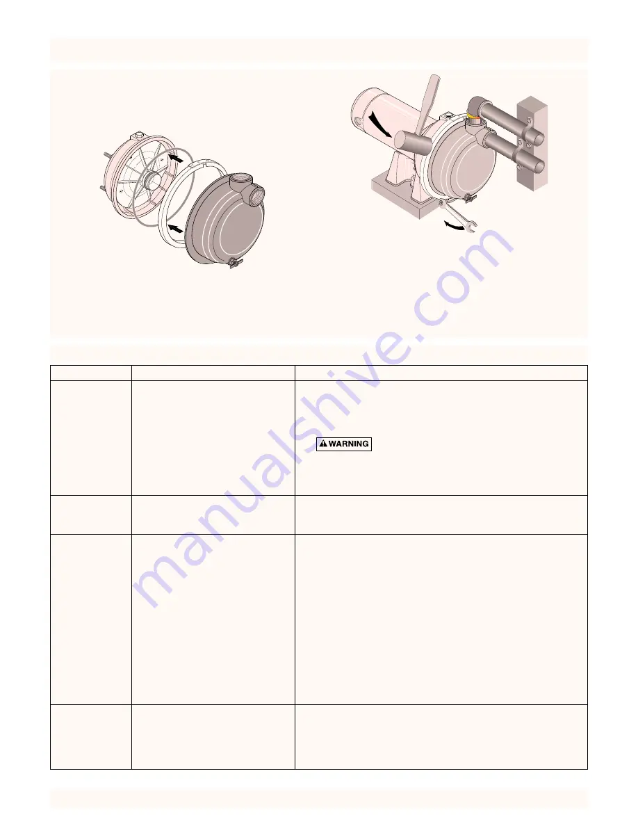
PUMP REASSEMBLY
1. Clean O-Ring and O-Ring groove.
2. Put O-Ring in groove on face of flange; put pump halves
together (see Figure 26).
3.
BE SURE
inside of clamp is clean. Place clamp on pump
halves; snug up. Alternately tighten screw and tap clamp
with mallet to seat O-Ring (see Figure 27).
4. Replace base mounting bolts.
5. Replace motor wiring; close draincock.
6. Prime pump according to instructions. See “Operation.”
7. Check for leaks.
L17
6-35P
854 0494
Figure 26 – Assemble Pump
Figure 27 – Tap Clamp While Tightening
P
856 0494
MAINTENANCE (Continued)


