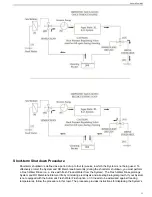
Caution:
If the Sea Recovery System is connected to a Sea Chest or Stand Up Pipe, do not plumb the Sea
Recovery System feed line to the top of these feed water arrangements. If plumbed to the top, the System
will intake air and experience continual shut down. The System's resulting failure will thus be attributed to
improper installation, will be the liability of the installer, and is not covered by the Sea Recovery Corporation
warranty. Ensure that the System is plumbed to the bottom of the feed water arrangements to ensure a
continual, air-free supply of Feed Water.
Sea Cock Valve
•
To be supplied by the System's Owner.
• Packing and connections must be tight and properly sealed.
• Clean the valve cavity of debris, or replace the seal, seat, or entire valve, as required.
• When System is in operation, this section is under vacuum conditions. Loose fittings or a worn seal will allow air
to enter the System, thereby causing continual shut down due to low Feed Water pressure.
Inlet Connection
Replace if damaged.
Sea Strainer
Keep the mesh screen free and clear of debris. When mesh screen is clogged, a low-pressure condition results
and causes System shut off. When System is in operation, this section is under vacuum conditions. If Sea Strainer’s
bowl is loose or the O-Ring seal is worn/improperly seated, the System will continually shut down due to low Feed
Water pressure.
Electric Motor and Booster Pump Assembly
Note:
Centrifugal, counter-clockwise rotation, as viewed from pump's volute (front) end.
Electric Motor
When troubleshooting electric-motor failure, check power, wiring, connections, contacts and the control circuit. A
failed electric motor requires repair or replacement. If failure is due to an external source (not the motor itself),
attempt to correct the cause to prevent future failure, and/or the need for replacement/repair. Electric motor failure
may be due to the following:
Generally caused by power that is outside the voltage range requirements of the system.
Winding failure
Generally caused by low power feeding the motor and/or low cycles from the power source. Also caused by rapidly repeating
the motor start and stop.
Capacitor failure
Attention:
The Booster Pump
must
rotate in the
counter-clockwise direction
. Rotating the Booster Pump in
the clockwise direction will cause extensive damage.
Attention:
When switching from 3-Phase Generator power to 3-Phase Shore power,
always
check phases
prior to operating the System. Otherwise, reverse rotation (and extensive damage) may occur when the power
is out-of-phase.
Electric-Motor Problems (caused by Booster Pump or Electric Motor) and Solutions:
1. The Single Phase (115 or 230VAC) Electric Motor “hums,” pulls starting current (locked rotor) amperage, does
not rotate, and trips the supply power circuit breaker when attempting to operate the System. The Single Phase
Electric Motor is a capacitor-start motor. If the motor was repeatedly and rapidly started with low voltage or a
drop in voltage occurred while starting, the capacitor will short out. Without the aid of a working capacitor, the
motor will “hum,” pull starting current (locked rotor) amperage, not rotate, and trip the supply power circuit
breaker when attempting to operate the System.
a. Check wiring size and connections to, from, and in between the Power Supply and the Electric Motor. Correct
wire size or any loose wires.
Aqua Matic XL 2200 - 3600
62
Содержание Aqua Matic XL Series
Страница 2: ......
Страница 10: ......
Страница 28: ......
Страница 38: ......
Страница 45: ...45 Commissioning...
Страница 46: ......
Страница 58: ......
Страница 76: ......
Страница 89: ...Chapter 10 Appendix 89...
Страница 90: ...ABS Certificate of Design Assessment Aqua Matic XL 2200 3600 90...
Страница 91: ...FCC Compliance 91 Appendix...
Страница 92: ...DNV ISO 9001 Certificate Aqua Matic XL 2200 3600 92...
Страница 93: ...Single Phase Electrical Motor Wiring 93 Appendix...
Страница 94: ...Three Phase Electrical Motor Wiring Aqua Matic XL 2200 3600 94...
Страница 95: ...Three Phase Transformer Wiring 95 Appendix...
Страница 96: ...New System Initial Readings Form Aqua Matic XL 2200 3600 96...
Страница 97: ...Daily System Readings 97 Appendix...
Страница 98: ......
Страница 99: ...Chapter 11 Exploded Parts Views 99...
Страница 100: ...Exploded Parts View...
Страница 103: ...7 8 9 10 11 12 13 14 15 16 17 20 19 18 21 22 23 24 25 26 1 2 3 4 5 6 Exploded Parts View 4...
Страница 107: ...6 10 14 10 6 10 4 10 13 8 14 10 6 5 7 7 5 11 12 3 2 3 3 2 3 10 4 7 9 7 1 4 Exploded Parts View 8...
Страница 111: ...14 13 2 16 13 12 3 8 10 9 7 1 5 4 6 14 13 15 15 17 13 12 11 18 15 Exploded Parts View 12...
Страница 113: ...19 16 2 21 16 14 3 9 11 10 8 1 5 4 6 12 22 20 18 16 17 15 15 13 7 Exploded Parts View 14...
Страница 115: ...2 3 10 12 11 9 1 5 4 21 13 20 18 15 19 18 19 15 17 14 16 8 18 15 7 Exploded Parts View 16...
Страница 117: ...10 26 11 9 5 5 4 20 1 7 18 3 2 16 13 15 12 14 13 23 24 21 24 25 Exploded Parts View 18...
Страница 119: ...12 10 13 11 5 5 4 6 1 9 20 3 2 17 16 14 18 15 19 17 16 14 18 15 8 7 Exploded Parts View 20...
Страница 128: ...6 7 2 3 2 5 10 10 12 1 11 8 9 8 11 6 7 4 2 13 14 29...
Страница 131: ...6 15 7 13 18 11 16 27 25 26 21 1 4 3 2 3 12 19 9 17 14 23 8 20 9 19 5 27 16 24 22 10 Exploded Parts View 32...
Страница 138: ...Chapter 12 Electric Diagrams Foldouts 101...
Страница 139: ...Aqua Matic XL Series Three Phase Wiring Diagram...
Страница 140: ......
Страница 141: ......
Страница 142: ...Sea Recovery 2630 E El Presidio Street Carson CA 90810 sales searecovery com www searecovery com PN B6513100001...


