


6.7
S
ECTION
6 • E
LECTRICAL
S
YSTEM
390 Sundancer
®
(
425 Sundancer
®
)
W
INDLASS
B
REAKER
(F
IG
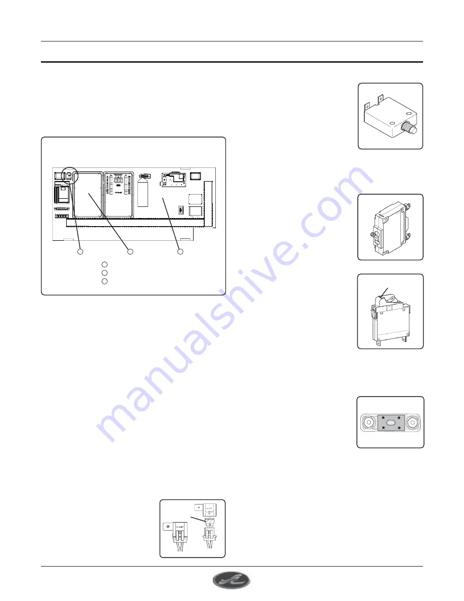
. 6.7.1)
WINDLASS BREAKER
MAIN BATTERY SOLENOID BOX
FORWARD BILGE
COMPONENT BOARD
A
A
A. W
INDLASS
B
REAKER
The breaker for the windlass is located on the
forward bilge component board left of the Main
Battery Solenoid Box (Figure 6.7.1).
B. R
EPLACING
A
F
USE
OR
B
REAKER
In the event it becomes necessary to replace a
fuse or an electrical breaker, REPLACE THE
FUSE OR BREAKER ONLY WITH A FUSE OR
BREAKER OF THE SAME RATING. The
amperage is marked on the fuse or breaker.
If a fuse or breaker is replaced with one of lower
amperage, it will be insufficient to carry the electrical
load of the equipment it is connected to and cause
nuisance tripping or blowing.
Conversely if a fuse or breaker is replaced with
one of higher amperage, it will not provide
adequate protection against an electrical
malfunction and could create a possible fire
hazard. Some of the various types of breakers
used on your boat are as follows:
This type is an in-line fuse
holder and uses an
automotive-type blade fuse.
B
This type of breaker is found
on the control station DC
breaker panel located behind
the access panel below the
control station switch panel.
These breakers protect the
trim tabs, wipers, windshield
vent, navigation lights, spot
light, engine synchronizer, horn, instrument lights,
12V receptacle and accessories.
This type of breaker is typically
found on the main distribution
panel. It selects the electrical
power source, either from the
generator or from shore power.
This type of breaker is found
on the main DC breaker panel.
It is used to protect the bilge
pumps, sump pumps, bilge
blowers, control station main,
electronics, systems monitor,
oil change pump, stereo
memory and accessories. This
is a manual reset breaker. It can be turned off by
inserting a small screwdriver in the slot on the toggle
switch.
This type is a current limiting
fuse which is used to isolate
faults in battery operated
systems and equipment
(motor circuits, panel feeders,
etc.).
C
B
C
SLOT FOR
DE-ENERGIZING
FUSE
Содержание 390 Sundancer
Страница 2: ...390 Sundancer 425 Sundancer ii THIS PAGE LEFT INTENTIONALLY BLANK...
Страница 12: ...390 Sundancer 425 Sundancer xii THIS PAGE WAS INTENTIONALLY LEFT BLANK...
Страница 30: ...390 Sundancer 425 Sundancer 1 18 SECTION 1 SAFETY THIS PAGE WAS INTENTIONALLY LEFT BLANK...
Страница 34: ...390 Sundancer 425 Sundancer 1 22 SECTION 1 SAFETY THIS PAGE WAS INTENTIONALLY LEFT BLANK...
Страница 80: ...390 Sundancer 425 Sundancer 3 18 SECTION 3 USING YOUR BOAT THIS PAGE WAS INTENTIONALLY LEFT BLANK...
Страница 96: ...390 Sundancer 425 Sundancer 4 16 SECTION 4 BILGE UNDERWATER GEAR THIS PAGE WAS INTENTIONALLY LEFT BLANK...
Страница 102: ...390 Sundancer 425 Sundancer 5 6 SECTION 5 FUEL SYSTEM THIS PAGE WAS INTENTIONALLY LEFT BLANK...
Страница 118: ...390 Sundancer 425 Sundancer 6 16 SECTION 6 ELECTRICAL SYSTEM THIS PAGE WAS INTENTIONALLY LEFT BLANK...
Страница 119: ...6 17 SECTION 6 ELECTRICAL SYSTEM 390 Sundancer 425 Sundancer DC WIRING SCHEMATIC FIG 6 17 1 Drawing No 09 601 1 0f 6...
Страница 120: ...390 Sundancer 425 Sundancer 6 18 SECTION 6 ELECTRICAL SYSTEM DC WIRING SCHEMATIC FIG 6 18 1 Drawing No 09 601 2 0f 6...
Страница 121: ...6 19 SECTION 6 ELECTRICAL SYSTEM 390 Sundancer 425 Sundancer DC WIRING SCHEMATIC GAS FIG 6 19 1 Drawing No 09 601 3 0f 6...
Страница 123: ...6 21 SECTION 6 ELECTRICAL SYSTEM 390 Sundancer 425 Sundancer Drawing No 09 601 5 0f 6 DC WIRING SCHEMATIC FIG 6 21 1...
Страница 124: ...390 Sundancer 425 Sundancer 6 22 SECTION 6 ELECTRICAL SYSTEM Drawing No 09 601 6 0f 6 DC WIRING SCHEMATIC FIG 6 22 1...
Страница 128: ...390 Sundancer 425 Sundancer 6 26 SECTION 6 ELECTRICAL SYSTEM ENGINE HARNESS SCHEMATIC FIG 6 26 1 Drawing No 09 604...
Страница 129: ...6 27 SECTION 6 ELECTRICAL SYSTEM 390 Sundancer 425 Sundancer SYSTEMS MONITOR WIRING DIAGRAM FIG 6 27 1 Drawing No 09 606...
Страница 130: ...390 Sundancer 425 Sundancer 6 28 SECTION 6 ELECTRICAL SYSTEM STOVE TOP SWITCH SCHEMATIC FIG 6 28 1 Drawing No 09 607...
Страница 131: ...6 29 SECTION 6 ELECTRICAL SYSTEM 390 Sundancer 425 Sundancer Drawing No 09 610 WINDLASS SCHEMATIC FIG 6 29 1...
Страница 132: ...390 Sundancer 425 Sundancer 6 30 SECTION 6 ELECTRICAL SYSTEM Drawing No 09 613 TV STEREO ANTENNA SCHEMATIC FIG 6 30 1...
Страница 133: ...6 31 SECTION 6 ELECTRICAL SYSTEM 390 Sundancer 425 Sundancer BOW THRUSTER SCHEMATIC FIG 6 31 1 Drawing No 09 616...
Страница 138: ...390 Sundancer 425 Sundancer 6 36 SECTION 6 ELECTRICAL SYSTEM STEREO WIRING DIAGRAM FIG 6 36 1 Drawing No 09 611...
Страница 139: ...6 37 SECTION 6 ELECTRICAL SYSTEM 390 Sundancer 425 Sundancer INTERCONNECT DIAGRAM FIG 6 37 1 Drawing No 09 622...
Страница 140: ...390 Sundancer 425 Sundancer 6 38 SECTION 6 ELECTRICAL SYSTEM THIS PAGE WAS INTENTIONALLY LEFT BLANK...
Страница 160: ...390 Sundancer 425 Sundancer 7 20 SECTION 7 ACCESSORIES AND OPTIONS THIS PAGE WAS INTENTIONALLY LEFT BLANK...
Страница 184: ...390 Sundancer 425 Sundancer Index 4 INDEX THIS PAGE LEFT INTENTIONALLY BLANK...


