7.8
S
ECTION
7 • O
PTIONS
& A
CCESSORIES
300 Sundancer
®
(335 Sundancer
®
)
HOLDING
TANK
DOCKSIDE PUMP-OUT
VENT FILTER
THRU-HULL
VENT
OVERBOARD
DISCHARGE
SEACOCK
HEAD
V
ACU
F
LUSH
®
H
EAD
W
ITH
H
OLDING
T
ANK
,
D
OCKSIDE
P
UMP
-O
UT
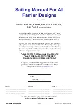
& O
PTIONAL
M
ACERATOR
(F
IG
. 7.8.2)
MACERATOR
(OPTIONAL)
VACU - GENERATOR
PORT
STBD
FWD
B. V
ACU
F
LUSH
®
H
EAD
The VacuFlush
®
head
utilizes a HEAD SYSTEM
breaker on the main
distribution panel. The foot
pedal at the base of the
toilet opens a mechanical
seal and vacuum forces
waste through the opening
in the bowl to an
accumulator tank, through
the vacuum pump and then
to the holding tank or treatment tank. To Operate:
1. Turn ON the WATER PUMP breaker.
2. Turn ON the HEAD SYSTEM breaker.
REFER TO OWNER’S MANUAL PACKET FOR
INSTRUCTIONS AND WARRANTY
INFORMATION.
V
ACU
F
LUSH
®
H
EAD
(F
IG
. 7.8.1)
A. R
EQUIREMENTS
FOR
O
PERATORS
The Environmental Protection Agency (EPA)
standards state that in freshwater lakes, freshwater
reservoirs or other freshwater impoundments
whose inlets or outlets are such as to prevent the
ingress or egress by vessel traffic subject to this
regulation, or in rivers not capable of navigation by
interstate vessel traffic subject to this regulation,
marine sanitation devices certified by the U.S. Coast
Guard installed on all vessels shall be designed and
operated to prevent the overboard discharge of
sewage, treated or untreated, or of any waste
derived from sewage. The EPA standards further
state that this shall not be construed to prohibit the
carriage of Coast Guard-certified flow-through
treatment devices which have been secured so as
to prevent such discharges. They also state that
waters where a Coast Guard certified marine
sanitation device permitting discharge is allowed
include coastal waters and estuaries, the Great
Lakes and interconnecting waterways, freshwater
lakes and impoundments accessible through locks,
and other flowing waters that are navigable
interstate by vessels subject to this regulation (40
CFR 140.3).
C. H
OLDING
T
ANK
O
PERATION
Waste from the head is directed into the holding
tank located in the engine room. The holding tank
fluid level indicator is located on the main distribution
panel or in the head which indicates 3/4 FULL, FULL
and DO NOT FLUSH, or on some models may read
FULL,1/2, or EMPTY. When the FULL light is on,
the DO NOT FLUSH light will also be on. When
these lights are ON, the holding tank must be
emptied before the head can be reused.
D
OCKSIDE
P
UMP
-
OUT
To empty holding tank, the services of a dockside
pump out station will be needed. Follow
instructions at the station and make sure pump
out station hose is inserted into the deck plate
marked WASTE. The holding tank can also be
emptied through utilization of the macerator (if
supplied) (see
Macerator
in this section).
Содержание 300 Sundancer
Страница 1: ...300 Sundancer International 335 Sundancer Owner s Manual Part Number MRP1815325 Sea Ray Owner s Manual...
Страница 2: ......
Страница 4: ...ii 300 Sundancer 335 Sundancer...
Страница 30: ...This page intentionally left blank...
Страница 54: ...3 10 SECTION 3 USING YOUR BOAT 300 Sundancer 335 Sundancer THIS PAGE LEFT INTENTIONALLY BLANK...
Страница 60: ...SECTION 4 BILGE UNDERWATER GEAR 4 6 300 Sundancer 335 Sundancer THIS PAGE LEFT INTENTIONALLY BLANK...
Страница 132: ...7 16 SECTION 7 OPTIONS ACCESSORIES 300 Sundancer 335 Sundancer THIS PAGE LEFT INTENTIONALLY BLANK...
Страница 154: ...9 4 SECTION 9 CARE REFINISHING 300 Sundancer 335 Sundancer THIS PAGE LEFT INTENTIONALLY BLANK...