68
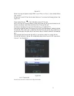
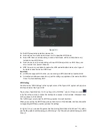
The Figure 6-58 and Figure 6-59 show that channels 1 to 16 are associated to HDD Group NO 1,
and channels 17 to 32 are associated to HDD Group NO 2. Therefore the records of channels 1 to
16 are stored into the hard disk(s) which belong to HDD Group NO 1, and the records of channels
17 to 32 are stored into the hard disk(s) which belong to HDD Group NO 2.
Important
Once you change the HDD Group settings, system will pack the records and snapshots, and then
reboot.
Figure 6-58
Figure 6-59
6.7.2
Abnormity
Abnormity interface is shown as in Figure 6-60.
Event type: There are several options for you such as disk error, no disk, disconnection,
IP conflict and etc.
Alarm output: Please select alarm activation output port (multiple choices).
Latch: Here you can set corresponding delaying time. The value ranges from 10s-300s.
System automatically delays specified seconds in turning off alarm and activated output after
external alarm cancelled.
Show message: system can pop up the message in the local screen to alert you when
alarm occurs.
Alarm upload: System can upload the alarm signal to the network (including alarm centre)
if you enabled current function.
Send email: System can send out email to alert you when alarm occurs.
Buzzer: Highlight the icon to enable this function. The buzzer beeps when alarm occurs.
Содержание The Networker POE series
Страница 1: ... The Networker POE Series DVR User s Manual 866 414 2553 ...
Страница 57: ...57 Figure 6 37 Figure 6 38 Figure 6 39 Figure 6 40 ...
Страница 78: ...78 Figure 7 5 ...
Страница 89: ...89 8 16 Figure 8 16 Figure 8 16 General Setup ...
Страница 102: ...102 Figure 8 32 UNPN 8 3 2 6 Alarm Alarm setup interface is shown as in Figure 8 33 Figure 8 33 Alarm Setup ...
Страница 129: ...129 Teclast Ti Cool 512M Teclast Ti Cool 1G Teclast Ti Cool 2G ...
Страница 137: ...137 Figure 14 12 ...


