16
Record light
1-16
It becomes on when system is recording.
IR Receiver
IR
It is to receive the signal from the remote control.
HDD abnormity
indicator
HDD
The red light is for the HDD abnormity
Network
abnormity
indicator
Net
The red light is for the network abnormity
2.1.2
2U Series
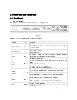
The 2U series NVR front panel is shown as in Figure 2-2.
Figure 2-2
Please refer to the following sheet for detail information.
Name
Icon
Function
Power button
Power button, press this button for three seconds to boot up or
shut down NVR.
Number button
0-9
Input Arabic number
Switch channel
Input
number
more than 10
-/--
If you want to input a number more than 10, please click this
button and then input.
Shift
In textbox, click this button to switch between numeral,
English(Small/Capitalized),donation and etc.
Enable or disable tour.
Up/
Down
、
Activate current control, modify setup, and then move up and
down.
Содержание The Networker POE series
Страница 1: ... The Networker POE Series DVR User s Manual 866 414 2553 ...
Страница 57: ...57 Figure 6 37 Figure 6 38 Figure 6 39 Figure 6 40 ...
Страница 78: ...78 Figure 7 5 ...
Страница 89: ...89 8 16 Figure 8 16 Figure 8 16 General Setup ...
Страница 102: ...102 Figure 8 32 UNPN 8 3 2 6 Alarm Alarm setup interface is shown as in Figure 8 33 Figure 8 33 Alarm Setup ...
Страница 129: ...129 Teclast Ti Cool 512M Teclast Ti Cool 1G Teclast Ti Cool 2G ...
Страница 137: ...137 Figure 14 12 ...


