14
Vario M
6.2
Segmentspannbüchse wechseln
Die Schraube (Pos. 3) mit einem Innensechskant-
schlüssel losdrehen und entfernen. Aufgesteckte Seg-
mentspannbüchse entfernen und die neue Büchse auf-
stecken. Darauf achten, dass die Bolzen (Pos. 6) der
Auswerfereinheit in die Nuten des Ringes (Pos. 5) sowie
die Nasen des Ringes in die Nuten der Büchse eingrei-
fen. Die Schraube (Pos. 3) wieder mit dem Innen-
sechskantschklüssel bis auf Block eindrehen. Hierbei
muss folgendes Drehmoment eingehalten werden:
6.2
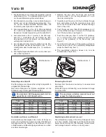
Changing the segmented clamping sleeve
Unscrew and remove the screw (item 3) with a hexagon
socket wrench. Remove the stuck-on segmented clamp-
ing sleeve and attach the new sleeve. Make sure that
the bolts (item 6) of the ejector unit engage in the
grooves of the ring (item 5) and the noses of the ring
engage in the grooves of the sleeve. Screw the screw
(item 3) back in with the hexagon socket wrench up to
the block. The following torque must be observed here:
Dorn-
größe
Gewinde
Zugbolzen
Empfohlenes
Anzugsmoment
M0
M7
10 Nm
M1
M8 x 1
15 Nm
M2
M14 x 1.5
25 Nm
M3
M20 x 1.5
45 Nm
Mandrel
size
Clamping bolt
thread
Recommended
torque
M0
M7
10 Nm
M1
M8 x 1
15 Nm
M2
M14 x 1.5
25 Nm
M3
M20 x 1.5
45 Nm
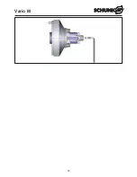
Um die Genauigkeit zu kontriollieren, muss der Zug-
bolzen und die Segmentspannbüchse entfernt werden.
Zugbolzen mit Innensechskantschlüssel losdrehen und
entfernen. Segmentspannbüche herunterziehen.
Die Schrauben herausschrauben und den Werk-
stückanschlag entfernen.
Für den Planlauf die Messuhr
auf die axiale
Anschlagfläche des Anschlags aufsetzen.
Für den Rundlauf die Messuhr auf den Außenkegel des
Dornkörpers aufsetzen.
Der Rundlauf des Dorns ist unmittelbar an die Aus-
richtung des Handspannfutters gebunden, je genauer
dieses ausgerichtet ist, desto genauer der Rundlauf
des Dorns.
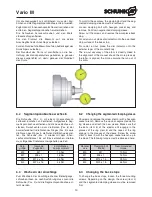
To monitor the accuracy, the clamping bolt and the seg-
mented clamping sleeve must be removed.
Loosen clamping bolt with hexagon socket key and
remove. Pull down segmented clamping sleeve.
Screw out the screws and remove the workpiece back
stop.
For axial run-out, place dial indicator onto the axial back
stop surface of the back stop.
For radial run-out, place the dial indicator onto the
external taper of the mandrel body.
The run-out accuracy of the arbor is directly linked to
the alignment of the manual chuck: the more precisely
the latter is aligned, the more accurate the run-out of
the arbor.
6.3
Wechseln der Anschläge
Zum Wechseln der Anschläge die drei Befestigungs-
schrauben lösen. Je nach Ausführung muss zuvor die
Schraube (Pos. 3) und die Segmentspannbüchse ent-
fernt werden.
6.3
Changing the back stops
To change the back stops, loosen the three mounting
screws. Depending on the design, the screw (item 3)
and the segmented clamping sleeve must be removed
first.
Содержание Vario M
Страница 22: ...22 Vario M ...


