SCHUNK PRG 100 Скачать руководство пользователя страница 3

Table of Contents

08.00 | PRG | Assembly and Operating Manual | en | 389325

3

Table of Contents

1

General....................................................................................................................  5

1.1

About this manual ................................................................................................  5
1.1.1

Presentation of Warning Labels ............................................................... 5

1.1.2

Definition of Terms................................................................................... 6

1.1.3

Applicable documents .............................................................................. 6

1.1.4

Sizes .......................................................................................................... 6

1.1.5

Variants..................................................................................................... 6

1.2

Warranty ..............................................................................................................  6

1.3

Scope of delivery ..................................................................................................  7
1.3.1

Accessories kit .......................................................................................... 7

1.4

Accessories ...........................................................................................................  8
1.4.1

Seal kit ...................................................................................................... 8

1.4.2

Mounting kit for proximity switch ............................................................ 8

2

Basic safety notes  ...................................................................................................  9

2.1

Intended use.........................................................................................................  9

2.2

Not intended use ..................................................................................................  9

2.3

Constructional changes ........................................................................................  9

2.4

Spare parts ...........................................................................................................  9

2.5

Gripper fingers ...................................................................................................  10

2.6

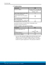
Ambient conditions and operating conditions ...................................................  10

2.7

Personnel qualification.......................................................................................  10

2.8

Personal protective equipment..........................................................................  11

2.9

Notes on safe operation .....................................................................................  11

2.10 Transport ............................................................................................................  11
2.11 Malfunctions.......................................................................................................  12
2.12 Disposal ..............................................................................................................  12
2.13 Fundamental dangers.........................................................................................  12

2.13.1 Protection during handling and assembly .............................................. 12
2.13.2 Protection during commissioning and operation ................................... 13
2.13.3 Protection against dangerous movements............................................. 13
2.13.4 Protection against electric shock............................................................ 14

2.14 Notes on particular risks.....................................................................................  14

3

Technical data......................................................................................................... 16

4

Assembly ................................................................................................................ 17

4.1

Installing and connecting....................................................................................  17

4.2

Connections........................................................................................................  19
4.2.1

Mechanical connection........................................................................... 19

4.2.2

Gripper finger ......................................................................................... 21

Содержание PRG 100

Страница 1: ...Translation of the original manual Assembly and Operating Manual PRG Pneumatic Radial gripper...

Страница 2: ...for the purpose of technical improvement Document number 389325 Version 08 00 15 05 2020 en SCHUNK GmbH Co KG All rights reserved Dear Customer thank you for trusting our products and our family owne...

Страница 3: ...ctional changes 9 2 4 Spare parts 9 2 5 Gripper fingers 10 2 6 Ambient conditions and operating conditions 10 2 7 Personnel qualification 10 2 8 Personal protective equipment 11 2 9 Notes on safe oper...

Страница 4: ...36 5 4 Product opens with heavy impacts in the end position 36 5 5 Gripping force is dropping 37 5 6 Product does not achieve the opening and closing times 37 6 Maintenance 38 6 1 Notes 38 6 2 Mainte...

Страница 5: ...manual Illustrations in this manual are provided for basic understanding and may differ from the actual product design In addition to these instructions the documents listed under Applicable documents...

Страница 6: ...ual applies to the following sizes PRG 26 PRG 34 PRG 42 PRG 52 PRG 64 PRG 80 PRG 100 PRG 125 1 1 5 Variants This operating manual applies to the following variations PRG without gripping force mainten...

Страница 7: ...screws 2x ID No of the accessory pack Accessory pack for ID number PRG 26 5517554 PRG 26 High temperature version HT 5517555 PRG 34 5517556 PRG 34 High temperature version HT 5517557 PRG 42 5517558 P...

Страница 8: ...ion HT 5521259 PRG 52 5521260 PRG 52 High temperature version HT 5521261 PRG 64 5521262 PRG 64 High temperature version HT 5521263 PRG 80 5521264 PRG 80 High temperature version HT 5521265 PRG 100 552...

Страница 9: ...r industrial and industry oriented use Appropriate use of the product includes compliance with all instructions in this manual 2 2 Not intended use It is not intended use if the product is used for ex...

Страница 10: ...t sufficiently qualified the result may be serious injuries and significant property damage All work may only be performed by qualified personnel Before working with the product the personnel must hav...

Страница 11: ...handling of the personnel Incorrect handling and assembly may impair the product s safety and cause serious injuries and considerable material damage Avoid any manner of working that may interfere wit...

Страница 12: ...er disposal 2 13 Fundamental dangers General Observe safety distances Never deactivate safety devices Before commissioning the product take appropriate protective measures to secure the danger zone Di...

Страница 13: ...remains and secure against inadvertent reactivation Never rely solely on the response of the monitoring function to avert danger Until the installed monitors become effective it must be assumed that...

Страница 14: ...verified by executing regular safety measurements 2 14 Notes on particular risks DANGER Risk of fatal injury from suspended loads Falling loads can cause serious injuries and even death Stand clear of...

Страница 15: ...NG Risk of injury due to spring forces Parts are under spring tension on products which clamp using spring force or which have gripping force maintenance While disassembling components can move unexpe...

Страница 16: ...t gripping force maintenance with gripping force maintenance 8 6 5 More technical data is included in the catalog data sheet Whichever is the latest version Ambient conditions and operating conditions...

Страница 17: ...of inertia of the fingers is exceeded the gripper can be damaged A jaw movement always has to be without jerks and bounce You must therefore implement sufficient reduction and or damping Observe the...

Страница 18: ...ssed air lines to the main air connections A and B Screw in air connections plug connections OR Screw on throttle valve in order to be able to perform sufficient throttling and or damping Screw the pr...

Страница 19: ...Requirements for evenness of the mounting surface Dimensions in mm Edge length Permissible unevenness 100 0 02 100 0 05 Connections at the base jaws Connections at the base jaws Item Mounting PRG 26 3...

Страница 20: ...romlocatingsurface mm 7 7 12 12 15 16 20 22 2 Centering sleeve 5 4 35 5 4 35 6 5 35 8 5 35 8 5 35 10 6 65 12 6 65 12 6 65 Side B 3 Mounting screw M2 5 M2 5 M3 M4 M4 M6 M6 M10 4 Centering sleeve 5 4 35...

Страница 21: ...ripper In order to avoid a collision between gripper finger and housing during opening and closing the gripper fingers the dimensions A to D must be strictly adhered to Design example of an gripper fi...

Страница 22: ...is exceeded the gripper can be damaged A jaw movement always has to be without jerks and bounce You must therefore implement sufficient reduction and or damping Observe the diagrams and information in...

Страница 23: ...f exceeding the maximum permissible weight per gripper finger Attach additional throttle screw connections to the module Adjust the opening and closing times depending on the mass moment of inertia of...

Страница 24: ...sensors and are available at schunk com Information on handling sensors is available at schunk com or from SCHUNK contact persons 4 3 1 Overview of sensors Overview of the compatible sensors Designat...

Страница 25: ...1 mm 26 30 22 2 42 90 33 7 26 60 24 1 52 30 30 7 26 90 26 4 52 60 34 8 34 30 23 8 52 90 39 6 34 60 26 3 64 30 34 5 34 90 29 3 64 60 39 4 42 30 26 8 64 90 45 1 42 60 29 9 NOTE The magnetic switch MMS 2...

Страница 26: ...3 Inductive proximity switch IN 40 NOTE The sensor can be used only for sizes 26 64 Mounting kit To use the inductive sensor the gripper has to be retrofitted with a special mounting kit This mounting...

Страница 27: ...er to the Open position and test the function Gripper closed Set the gripper to the Closed position Carefully push proximity switch 2 into the bracket 4 until it touches the switch cam 10 Pull the pro...

Страница 28: ...screw and the nut 5 6 on the bracket 3 4 Fasten brackets 3 4 with screws 7 8 and washers 13 14 to the housing Push the brackets down as far as pos sible away from the rotary bolt Fasten the switch ca...

Страница 29: ...e stop of the bracket 4 Fasten the proximity switch by tightening the screws 6 in the bracket Undo screws 8 and carefully push bracket 4 to the switch cam until it touches the switch cam 12 Pull the b...

Страница 30: ...ening torque If the threaded pin is tightened with an incorrect tightening torque the product may be damaged Observe a maximum tightening torque of 10 Ncm for the set screws The RMS sensors have a lar...

Страница 31: ...d Set the gripper to the Closed position Slide the magnetic switch 2 2 into the groove 4 in the direction of the center of the gripper until it switches By tightening the set screw 3 fix the magnetic...

Страница 32: ...dimension l1 In Optimal Mode the sensor identifies the optimal position in the groove itself SCHUNK recommends Optimal Mode for setting the sensors Setting the sensor in Optimum mode Put product in t...

Страница 33: ...e the sensor 1 1 into the groove 2 until the sensor 1 1 stops at the T nut 3 Secure the sensor 1 1 using the set screw 4 Tightening torque 10 Ncm Adjust sensor 1 1 see sensor assembly and operating ma...

Страница 34: ...Observe the maximal tightening torque NOTE If there is no T nut available slide the sensor according to dimension I1 into the groove 2 Setting dimensions for magnetic switches 25 Turn the sensor 1 int...

Страница 35: ...uring assembly Observe the maximal tightening torque NOTE The sensor can be used only for sizes 26 64 Turn the sensor 1 into the groove 2 OR Slide the sensor 1 into the groove 2 until the sensor 1 sto...

Страница 36: ...ssible cause Corrective action Dirt deposits between cover and piston Clean and if necessary re lubricate Maintenance 38 Pressure drops below minimum Check air supply Air connection 22 Mounting surfac...

Страница 37: ...control couplings on the product to the maximum that the movement of the jaws occurs without bouncing and hitting Check compressed air lines Inner diameters of compressed air lines are of sufficient s...

Страница 38: ...aws as a set 6 2 Maintenance interval CAUTION Material damage due to hardening lubricants Lubricants harden more quickly at temperatures above 60 C leading to possible product damage Reduce the lubric...

Страница 39: ...the cover 4 out of the housing Unscrew and remove the screws 6 Pull cylinder piston 5 out of the housing Loosen set screw 20 in the base jaws 2x Remove rotary bolt 6 2x Remove base jaws 2 2x Pull pis...

Страница 40: ...base jaws 2x Remove rotary bolt 6 2x Remove base jaws 2 2x Pull piston rod 3 out of the housing 6 5 Disassembly of PRG 80 125 6 5 1 Version without gripping force maintenance Position of the item num...

Страница 41: ...that no residual energy remains in the system WARNING Risk of injury due to spring forces The cylinder piston is under spring tension Carefully disassemble the product Remove the compressed air hoses...

Страница 42: ...t Seal kit 8 Assembly Assembly takes place in the opposite order to disassembly Observe the following Unless otherwise specified secure all screws and nuts with Loctite no 243 and tighten with the app...

Страница 43: ...d assignment of the spare parts Variations are possible depending on size and variant 6 7 1 Assembly drawing PRG 26 64 Assembly of the Types O D gripping I D gripping without gripping force maintenanc...

Страница 44: ...6 7 2 Assembly drawing PRG 80 125 Assembly of the Types O D gripping I D gripping without gripping force maintenance Wearing part replace during maintenance Included in the seal kit Seal kit can only...

Страница 45: ...0303678 0303681 0303688 0303691 0303698 0303701 0303708 39303651 39303658 39303661 39303668 39303671 39303678 39303681 39303688 39303691 39303698 39303701 39303708 The partly completed machine may not...

Страница 46: ...303701 39303708 To be provided by the System Integrator for the overall machine Fulfilled for the scope of the partly completed machine Not relevant 1 1 Essential Requirements 1 1 1 Definitions X 1 1...

Страница 47: ...guards and protective devices 1 4 1 General requirements X 1 4 2 Special requirements for guards X 1 4 2 1 Fixed guards X 1 4 2 2 Interlocking movable guards X 1 4 2 3 Adjustable guards restricting ac...

Страница 48: ...from here forward 2 Supplementary essential health and safety requirements for certain categories of machinery X 2 1 Foodstuffs machinery and machinery for cosmetics or pharmaceutical products X 2 2 P...

Отзывы: