background image

14

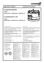
Montage- und Betriebsanleitung für
Ausgleichseinheit

Type AGE-XY

Assembly and Operating Manual for
Compensation unit

Type AGE-XY

ACHTUNG!

Das max. Anzugsmoment der Näherungsschalter-
Schraube beträgt 15 Ncm.

Ausgleichseinheit »verriegelt«:

1.

Verriegeln Sie die AGE, indem Sie den Anschluss

B

mit

Druck beaufschlagen.

2.

Schieben Sie den Magnetschalter

1

in die Profilnut bis dieser

schaltet.

3.

Fixieren Sie den Magnetschalter

1

in dieser Stellung mit der

Schraube im Magnetschalter.

4.

Testen Sie die Funktion, indem Sie die AGE entriegeln und
verriegeln.

Ausgleichseinheit »entriegeln«:

1.

Entriegeln Sie die AGE, indem Sie den Anschluss

A

mit

Druck beaufschlagen.

2.

Schieben Sie den Magnetschalter

2

in die Profilnut bis dieser

schaltet.

3.

Fixieren Sie den Magnetschalter

2

in dieser Stellung mit der

Schraube im Magnetschalter.

4.

Testen Sie die Funktion, indem Sie die AGE verriegeln und
entriegeln.

CAUTION!

The maximum starting torque of the proximity switch
screw is 15 Ncm.

”Locking” of the compensation unit:

1.

Lock the AGE unit by actuating connection

B

with compres-

sed air.

2.

Move the solenoid switch

1

into the groove of the profile until

it switches.

3.

Locate the solenoid switch

1

in this position with the screw

inside the solenoid switch.

4.

Control proper function by unlocking and locking the AGE
unit.

”Unlocking” of the compensation unit:

1.

Unlock the AGE unit by actuating connection

A

with compres-

sed air.

2.

Move the solenoid switch

2

into the groove of the profile until

it switches.

3.

Locate the solenoid switch

2

in this position with the screw

inside the solenoid switch.

4.

Control proper function by locking and unlocking the AGE
unit.

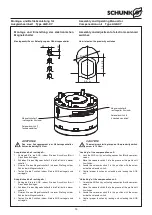
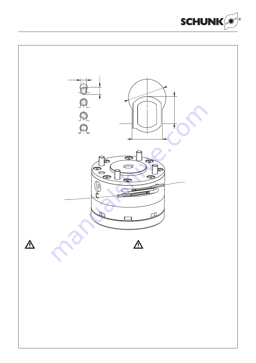
Magnetschalter

2

»entriegelter Zustand«

Solenoid switch

2

“unlocked condition”

Magnetschalter

1

»verriegelter Zustand«

Solenoid switch

1

“locked condition”

Montage und Einstellung der elektronischen
Magnetschalter

Montageschritte zur Befestigung der Näherungsschalter

Assembly and adjustment of electronic solenoid
switches

How to fasten the proximity switches

3.1

3

.

9

2

.

5

-

2

.

8

3.

4

– 0

– 0

.1

Ø

4

.1

±

0

.1

Содержание AGE 50-XY

Страница 1: ...6 21 51760267 info cn schunk com www cn schunk com CZECH REPUBLIC SCHUNK Intec s r o Tel 420 531 022066 Fax 420 531 022065 info cz schunk com www cz schunk com DENMARK SCHUNK Intec A S Tel 45 43601339...

Страница 2: ...Gew hrleistung Warranty 4 3 Lieferumfang Scope of delivery 5 4 Technische Daten Technical Data 5 5 Montage Assembly 5 5 1 Befestigung der AGE an Roboter Mounting the AGE on a robot 5 5 2 Luftanschluss...

Страница 3: ...splayed wherever there is a danger of injury or where the unit may suffer damage 1 2 Appropriate use The unit is intended for installation mounting for machinery and equipment The requirements of the...

Страница 4: ...e bei den Ver kaufs und Lieferbedingungen Die Einheit gilt dann als defekt wenn deren Grundfunktion Greifen oder Schwenken nicht mehr gegeben ist 7 Always disconnect the power supply lines during as s...

Страница 5: ...sind vormontiert Zur Zentrierung der AGE kann der Zylinderstift Pos 70 ver wendet werden 3 Scope of delivery AGE Fastening screws Cylindrical pin 4 Technical Data see catalog The air borne noise emit...

Страница 6: ...TUNG Beachten Sie unbedingt die Sicherheitshinweise auf den Seiten 3 und 4 Um die Funktion der AGE zu erhalten beachten Sie bitte folgen de Hinweise 1 Druckmittel Druckluft Anforderung an die G teklas...

Страница 7: ...e gr ndlich und pr fen Sie alle Teile auf eventuelle Defekte und Verschleiss 10 Erneuern Sie alle Dichtungen gem Dichtsatzliste siehe Kapitel 9 1 Der komplette Dichtsatz ist bei Fa SCHUNK erh ltlich D...

Страница 8: ...GE XY Assembly and Operating Manual for Compensation unit Type AGE XY 8 Zusammenbauzeichnung 8 Assembly drawing 40 6 4 32 31 60 54 2 30 52 3 28 34 8 52 3 28 34 51 51 7 41 4 32 60 9 44 33 53 33 5 43 1...

Страница 9: ...ption Menge Quantity 28 9611 081 O Ring O ring 6 x 1 5 2 29 9611 159 O Ring O ring 12 x 1 5 1 30 9611 063 O Ring O ring 6 x 1 2 31 9610 009 Quad Ring Square ring 15 6 x 1 78 2 32 9937 421 Quad Ring Sq...

Страница 10: ...0 M6 x 12 1 54 9682 086 Zylinderstift Cylinder pin DIN EN ISO 8734 2 0 M6 x 10 1 60 9938 122 Rundmagnet Circular magnet DRM 1 5 x 2 1 70 9682 023 Zylinderstift Cylinder pin DIN EN ISO 8734 6 0 M6 x 12...

Страница 11: ...N ISO 8734 5 0 M6 x 12 1 54 9682 086 Zylinderstift Cylinder pin DIN EN ISO 8734 2 0 M6 x 10 1 60 9182 520 Rundmagnet Circular magnet DRM 2 x 4 1 70 9682 023 Zylinderstift Cylinder pin DIN EN ISO 8734...

Страница 12: ...derstift Cylinder pin DIN EN ISO 8734 5 0 M6 x 12 2 53 9682 024 Senkschraube Countersunk screw DIN EN ISO 10642 A2 M6 x 16 1 60 9182 520 Ringmagnet Ring magnet DRM 2 x 4 1 70 9682 089 Zylinderstift Cy...

Страница 13: ...rom der einzelnen Sensoren ca 2 mA addiert 10 Accessories on separate order 10 1 Proximity switch Electronic solenoid switch Technical data Supply voltage 10 30 V DC Operation voltage 15 Max load curr...

Страница 14: ...ing torque of the proximity switch screw is 15 Ncm Locking of the compensation unit 1 Lock the AGE unit by actuating connection B with compres sed air 2 Move the solenoid switch 1 into the groove of t...

Страница 15: ...soll den Bestimmungen der Richtlinie Maschinen 2006 42 EG entspricht Angewandte harmonisierte Normen insbesondere EN ISO 12100 1 Sicherheit von Maschinen Grundbegriffe allgemeine Gestaltungsleits tze...

Страница 16: ...incomplete machine is to be installed with the provisions of the Machinery Directive 2006 42 EC is confirmed Applied harmonized standards especially EN ISO 12100 1 Safety of machinery Basic concepts...

Отзывы: