background image

4

Operating instructions

Solenoid interlock

MZM 100

MZM 100 B

EN

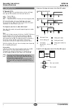
At an ambient temperature of ≥ 50 °C, the safety 

component must be fitted so that it is protected against 

unintentional contact with persons

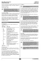
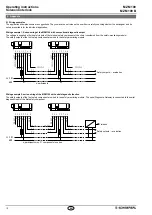
The safety component must be operated in the operating 

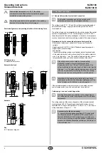
direction of the latching force (refer to image)

Axial misalignment and operating direction of the latching force

±

5m

m

±

3 mm

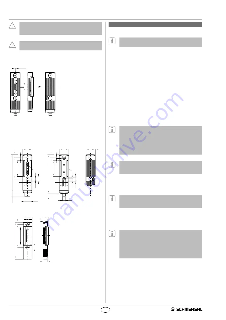
3.2  Dimensions

All measurements in mm

Solenoid interlock

40

6.2

68

92

162.5

16.3

13

5

40

1

M

M23

15.6 

10.6 

ST2

11.2 

40

M12

68

92

165.5

11.8

13

5

M

6.2

15.6 

10.6 

11.2 

ST

Actuator

40

24

20

5

3

10

0

16

0

9

78

20

6.2

8

Key

M Permanent magnet

4.  Electrical connection

4.1  General information for electrical connection

The electrical connection may only be carried out by  

authorised personnel in a de-energised condition 

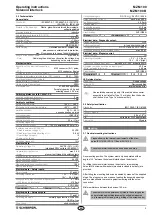
The voltage inputs A1, X1, X2 and IN must have a protection against 

permanent overvoltage  supply units according to IEC 60204-1 is 

recommended

The safety outputs can be integrated into the safety circuit of the control 

system For applications of PL e / control category 4 to ISO 13849-1, 

the safety outputs of the safety switchgear or the chain of components 

must be connected to a safety-monitoring module of the same category

Requirements for the connected safety-monitoring module:

•  Dual-channel safety input, suitable for 2 p-type semi-conductor 

outputs

•  Digital inputs to EN 61131-2, Table "Standard operating ranges for 

digital inputs (current sinking)"

• 


Test function  

The safety-monitoring module must tolerate internal functional tests 

of the solenoid interlock with cyclic switch-off of the safety outputs for 

max 2 ms (typically < 1 ms) The switch-off stage of the test cycle is 

temporarily reduced by an active ohmic discharge of the cable

If the safety sensor is connected to electronic safety-

monitoring modules, we recommend that you set a 

discrepancy time of min 100 ms The safety inputs of the 

safety-monitoring module must be able to blank a test impulse 

of approx 1 ms The safety-monitoring module does not need 

to have a cross-wire short monitoring function, if necessary, 

the cross-wire short monitoring function must be disabled

Information for the selection of suitable safety-monitoring 

modules can be found in the Schmersal catalogues or in the 

online catalogue on the Internet: wwwschmersalnet

If the solenoid interlock is wired to relays or to non-safety relevant 

control components, a new risk analysis must be carried out

Cable design in case of serial diagnostics

On wiring SD devices, pay attention to the voltage drop on 

the cables and the current carrying capacity of the individual 

components

The wiring capacity of the connecting cable of the solenoid interlock 

must not exceed 50 nF Depending on the strand structure, normal 

unshielded 30 m long control cables LIYY 025 mm² to 15 mm² have a 

wiring capacitance of approx 3 … 7 nF

Accessories for the series-wiring

For convenient wiring and series-wiring of SD components, 

the SD junction boxes PFB-SD-4M12-SD (variant for the 

field) and PDM-SD-4CC-SD (variant for control cabinet on 

carrier rail) are available along with additional comprehensive 

accessories Detailed information available on the internet at 

wwwschmersalnet

Содержание MZM 100

Страница 1: ...ively used in accordance with the versions listed below or for the applications authorised by the manufacturer Detailed information regarding the range of applications can be found in the chapter Product description 1 5 General safety instructions The user must observe the safety instructions in this operating instructions manual labelled with the caution or warning symbol above the country specif...

Страница 2: ...e upon request or can be downloaded from the Internet at www schmersal com 2 4 Purpose The safety switchgears are classified according to ISO 14119 as type 4 interlocking devices The MZM 100 is designed for application in safety circuits and is used for monitoring the position of movable separating safety guards A door detection sensor monitors the closed condition of the safety guard The optional...

Страница 3: ...se duration on input signal 1 0 ms With test pulse interval of 100 ms Classification ZVEI CB24I Countersink C1 Source C1 C2 C3 Electrical data Safety outputs Safety outputs Y1 and Y2 Switching elements normally open function 2 channel OSSD p type Fuse rating short circuit proof Utilisation category DC 13 Ue Ie 24 VDC 0 25 A Rated operating current Ie each max 0 25 A Leakage current Ir 0 5 mA Volta...

Страница 4: ...tolerate internal functional tests of the solenoid interlock with cyclic switch off of the safety outputs for max 2 ms typically 1 ms The switch off stage of the test cycle is temporarily reduced by an active ohmic discharge of the cable If the safety sensor is connected to electronic safety monitoring modules we recommend that you set a discrepancy time of min 100 ms The safety inputs of the safe...

Страница 5: ...prox 100 N To this end the adjustment target MZM 100 TARGET is used directly on the fitted MZM 100 Adjustment of the latching force 1 Open the safety guard and isolate the MZM 100 from the voltage supply Either switch off the voltage supply or pull out the connector 2 Put the adjustment target with the active side on the identification plate of the MZM 100 3 Switch the voltage supply of the MZM 10...

Страница 6: ...cross wire short will lead to a delayed shut down refer to table 2 After the rectification of the error the error message is reset by opening the corresponding safety guard Error warning A fault has occurred which causes the safety outputs to be disabled after 30 minutes The safety outputs initially remain enabled This enables the shutdown of the process in a controlled manner An error warning is ...

Страница 7: ...en 0 V On Off Off 0 V 0 V Safety guard closed actuator in safety guard can be locked 0 V On Off Flashes 24 V 24 V Safety guard closed and locked 24 V On Off On 24 V 24 V Solenoid interlock cannot be locked Safety guard not correctly closed or magnet soiled 24 V On Off Off 0 V 0 V Error warning1 actuator in 0 V 24 V On Flashes 2 flashes on 24 V 0 V Error 0 V 24 V On Flashes 2 Off 0 V 0 V 1 after 30...

Страница 8: ... diagnostic channels are wired in series The diagnostic data are transmitted through the series wiring of the inputs and outputs Max 31 safety switchgear with serial diagnostics can be wired in series For the evaluation of the serial diagnostics line either the PROFIBUS Gateway SD I DP V0 2 or the Universal Gateway SD I U are used This SD Gateway is integrated as a slave in an existing field bus s...

Страница 9: ...tatus signals and the safety outputs by means of an example of MZM 100 variant Solenoid interlock monitored System condition LED Safety outputs Response byte bit n green red yellow Y1 Y2 7 6 5 4 3 2 1 0 Safety guard open On Off Off 0 V 0 0 0 X 0 0 0 0 Safety guard closed actuator in On Off Flashes 0 V 0 0 0 X 0 0 1 0 Safety guard closed and locked On Off On 24 V 0 0 0 X 0 1 1 1 Solenoid interlock ...

Страница 10: ...t safety component are wired to the safety monitoring module X1 Y1 X2 Y2 1 2 3 5 6 8 X1 X2 A1 A2 Y1 Y2 1 2 3 5 6 8 X1 4 Y1 4 Y1 X2 7 Y2 7 Y2 OUT A1 A2 OUT SPS PLC IN SPS PLC SPS PLC IN 24 VDC GND SPS PLC n participants Safety outputs evaluation Wiring example 2 series wiring of the MZM 100 with serial diagnostic function The safety outputs of the first safety component are wired to the safety moni...

Страница 11: ...t 1 4 4 YE BK OUT Diagnostic output SD output 5 5 GY GY X2 Safety input 2 6 6 PK PK Y2 Safety output 2 7 7 BU VT IN Solenoid control SD input 8 8 RD OR without function 9 Connector plug ST M23 8 1 pole Connector plug ST2 M12 8 pole 1 2 9 3 4 5 6 7 8 5 8 4 3 2 1 7 6 Connecting cables with female connector IP67 M23 8 1 pole 8 x 0 75 mm Connecting cables with coupling female IP67 IP69 M12 8 pole 8 x ...

Страница 12: ...6 2011 Notified body which approved the full quality assurance system referred to in Appendix X 2006 42 EC TÜV Rheinland Industrie Service GmbH Alboinstr 56 12103 Berlin ID n 0035 Person authorised for the compilation of the technical documentation Oliver Wacker Möddinghofe 30 42279 Wuppertal Place and date of issue Wuppertal December 2 2016 Authorised signature Philip Schmersal Managing Director ...

Отзывы: