
6
Operating instructions
Solenoid interlock
MZM 100
MZM 100 B
EN
6. Diagnostic functions
6.1 Diagnostic LED's
The MZM 100 signals the operational state as well as errors through
three coloured LED’s installed on the front side of the device
green
Supply voltage on
yellow
Operating condition
red
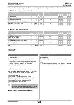
Fault (refer to table 2: Flash codes of the red diagnostic LED)
6.2 Solenoid interlock with conventional diagnostic output
The short-circuit proof diagnostic output OUT can be used for central
visualisation or control functions, eg in a PLC
The diagnostic output is not a safety-related output!
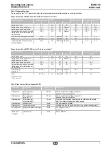
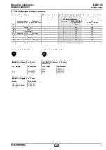
Depending on the variant used, specific diagnostic signals are emitted
(refer to table 1)
Error
Errors, which no longer guarantee the function of the MZM 100 solenoid
interlock (internal error)s cause the safety outputs to be disabled
within the risk time Any error that does not immediately affect the
safe functionality of the MZM 100 solenoid interlock (eg the ambient
temperature too high, interference potential at a safety output,
cross-wire short) will lead to a delayed shut-down (refer to table 2)
After the rectification of the error, the error message is reset by opening
the corresponding safety guard
Error warning
A fault has occurred, which causes the safety outputs to be disabled
after 30 minutes The safety outputs initially remain enabled
This enables the shutdown of the process in a controlled manner
An error warning is deleted when the cause of error is eliminated
If more than one fault is detected at the safety outputs,
the component will be electronically locked and a normal
fault reset will no longer be possible
To reset this type of interlocking, the component must be
isolated from the power supply after elimination of the error
causes
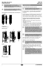
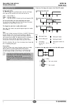
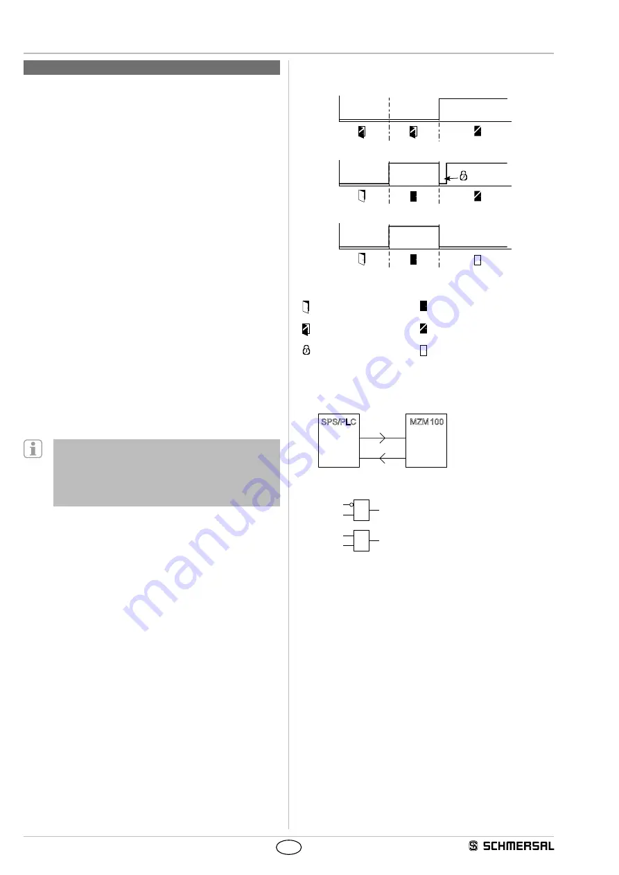
Behaviour of the diagnostic outputs of the W and W2 variants
Input signal magnet control
IN
Normal sequence, door was locked
OUT
Door could not be locked or fault
OUT
Key
Safety guard open
Safety guard closed
Unlock safety guard
Safety guard locked
Locking time
typically: 100 150 ms
max: 1 s
Safety guard not locked or
fault
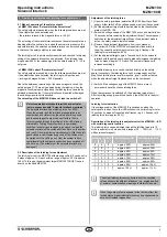
Evaluation of the diagnostic outputs of the W and W2 variants
SPS/PLC
MZM 100
I N
O U T
E 1 . 0
A 1 . 0
M 1 . 0
M 2 . 0
A 1 . 0
E 1 . 0
&
A 1 . 0
E 1 . 0
&
Door can be locked
IN = 1 = locking
Door is locked


