Assembly
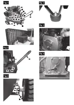
Transport hanger Fig. 2
Insert the transport hanger (1) on each side into
the sockets (a)
and secure them with 2 hex socket head cap
screws.
Wheels, Fig. 3
1 To attach the wheels, first guide the bolts
(a) through the wheel (12).
2 Slide the wheel unit through the lug under
the tank
3 Attach this with a washer (c), a safety disc
(d) and a nut (e) and secure these tightly.
4 Repeat this procedure for the second
wheel.
Rubber Bumper, Figure 4
Secure the rubber bumper on the bracket on the
front side of the tank. Use the enclosed screws,
washers, and nuts.
Oil, Figure 5, 6
Warning: It is imperative that you check the
oil level before using the machine for the
first time!
Operation of the machine without oil will cause
irreparable damage and invalidate the guaran
-
tee.
1
Remove the plastic oil filler plug located in
the crank box of the compressor housing.
2
Fill the crankcase with oil, until the oil level
in the oil-level indicator (16) reaches the
centre of the circular marking.
3
Close the opening using the sealing plug
(14) included in the delivery.
Putting into operation
Warning:
It is absolutely necessary to check the oil fill
level before the first use!
1
Make sure the place of setting up is clean,
dry, and well vented.
2
Make sure that the oil level is correct and
that the air filters are installed.
3
Start the compressor as described in the
chapter „Switching on and off the compres-
sor“. At switching on for the first time, let the
compressor run for ten minutes at no load
with the drain valve open, so that all the
parts get well lubricated.
Warning:
As compressed air comes off the out
-
put, the output may not be directed towards the
operator or people in the vicinity. The air coming
off the exit may not be inhaled. Daily check the
pressure control valve.
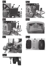
Switching on and off the compressor, Fig. 7
1
Check the model plate on the compressor:
230 – 240 V (or 110 – 120 V).
2
Plug the compressor cable into a standard
socket (240 V or 120 V) and switch the
compressor on.
3
For switching the compressor on, lift the
ON/OFF switch (3) on the pressure switch
cover (2).
4
For switching the compressor off, depress
the ON/OFF switch.
Operation
Fig. 8
1
The pressure in the tank is controlled by the
pressure switch under the pressure switch
cover (2). When the maximum pressure set
is reached, the pressure switch is activated
and the motor switched off. The pressure is
reduced as the air is consumed by the
connected tool, until the minimum pres-
sure set is reached. Then the pressure
switch re-engages the motor. The operator
at the compressor should take care that
the motor engages and disengages dictated
by the influence of the increasing and
decreasing pressure in the tank. The motor
engages without any previous warning.
2
The maximum and minimum pressure have
been set in the works. These settings may
not be altered.
3
All accessories were connected to the
adjustable drain valve (6).
4
As shown on the adjustable output pressure
gauge (4), the pressure of the adjustable
exit can be altered by turning the adjustable
button (5).
Attention:
In order to read the correct output
at the output gauge, air must flow through the
output. The adjustable valve must be set and the
pressure gauge read with the valve open, while
the air flows from the output set through the
accessory.
Turn the pressure regulator clockwise to increa
-
se the air pressure. Turn the pressure regulator
anticlockwise to reduce the air pressure.
Attention:
The absence of air flow during set
-
ting produces an incorrect display. For a correct
display, air must flow.
5
Upon termination of your work, or when you
leave the compressor unattended, switch it
off as follows:
• Press the ON/OFF switch (3).
• Wait until the compressed air has escaped
via the drain valve under the switch cover
(2).
Attention:
On pressing the button you should
hear a short air exit (about half a second).
Fig. 9
• Switch the machine off and pull the mains
plug.
• Pull the ring on the safety valve (8) in
order to make sure that the compressed air
has escaped from the tank, or open the
drain plug of the tank in order to let the
pressure escape.
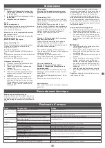
Maintenance
Attention!
1 Unplug the power supply before all
cleaning and maintenance work.
2 Allow the compressor to cool down;
burn hazard.
3 Depressurise the tank.
Fig. 10
Condensation water
After every day in operation, use the drain screw
(11) under the tank to drain off the condensate.
Attention!
The condensate contains oil residues.
Dispose of the condensation water in an en-
vironmentally sound way at an appropriate
collection point.
Oil level Fig. 11
Place the compressor on an even surface.
The oil level should be between Max und Min
in the display window (17).
The recommended oil is 15W/40 or equivalent.
The first oil change should be carried out after
100 hours of use.
After this, change the oil after every 500 hours
of use.
Oil change Fig. 11
1 Stop the engine and remove the plug.
2 Drain the compressed air.
3 Place a waste container under the oil drain
screw (16).
4 Undo the oil drain screw (16).
5 Drain the oil (tilt the compressor slightly so
that all the oil can drain out).
6 Close the oil drain screw (16).
7 Pour oil into the oil fill up to the mark in the
display window (17) and close the sealing
plugs (14).
Used oil
Dispose of the used oil in an environmen-
tally sound way at an appropriate collection
point.
Air filter Fig 12.13
Regularly check the inner air filter. Remove the
two hex cap screws (a) and remove the air filter
from the cylinder head. Open the two casing
shells (b) and remove the filter (c). Clean all the
parts by tapping them or with low-level air pres
-
sure (approx. 3 bar). After cleaning, reassemble
the filter and screw it back onto the cylinder
head.
13
D
GB
Содержание 4906116901
Страница 2: ...D Kompressor 5 9 GB Compressor 10 14 FR Compresseur 15 19...
Страница 4: ...Fig 7 Fig 9 Fig 10 11 Fig 8 2 3 2 5 6 4 8 Fig 11 14 16 17 Fig 12 a Fig 13 d c b...
Страница 20: ......
Страница 22: ......


