Installation, Mounting and Maintenance DISA-360
Construction subject to change.
No return possible!
Version:
When charging the register, make sure by means of on-site ven-
tilation devices that no air remains in the hydraulic circuit.
If the unit is to be installed at a location having temperatures be-
low zero degrees, glycol must be admixed to the coolant in a
suitable ratio, to ensure that the freezing point of this liquid al-
ways stays below the minimum temperature of the operating
site. Please note that the use of an antifreeze necessarily results
in a loss in performance of the register.
Connecting the air ducts
The air ducts are attached by using pipe clamps, fixing lugs or
the like.
Optionally, a rubber lip seal can
be installed on the connection
pipe, to ensure tightness be-
tween the device and the pipes.
Mounting accessories
Valves and actuators
Valves and actuators shall not be installed ex works. During in-
stallation the manufacturer's specifications must be observed.
Temperature controls
The temperature controls are mounted in accordance with the
selected model. This is why the instructions enclosed with each
model must be followed. However, in order to achieve optimum
measurement by the sensors, the following basic information
should be observed:
Condensate monitor
The installation of a condensate monitor depends on the select-
ed model. Please follow the instructions enclosed with each
model.
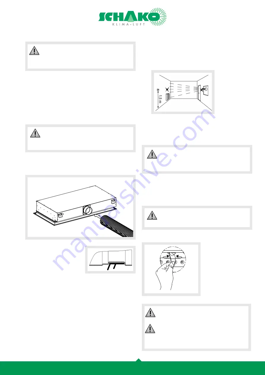
Adjustment of the air deflection blades
To regulate the air flow, ro-
tate the air deflection blades
manually.
With blockwise adjustable
blades, 5 blades can be ad-
justed simultaneously.
In order to achieve a uniform cooling capacity, the
ceiling induction diffusers type DISA-360 should be
connected to the cold water distribution system in
parallel.
The ceiling induction diffusers type DISA-360 are
induction devices for "dry cooling". To avoid con-
densates, the water inlet temperature should be
higher than the dew point.
- Do not mount the temperature control close to or above a
heat source (direct sunlight, lamps, television sets, radia-
tors, etc.), in places with draught air or directly opposite
to an air diffuser grille.
- Temperature controls must be mounted at least 1.5 me-
tres above the floor.
- Mounting temperature controls on walls toward the out-
doors should be avoided.
Before drilling, make sure that no electric cables
are present in the wall where the temperature con-
trol is to be mounted.
is attached no electric cables are present.
Faulty mounting of the sub-assemblies and of the
accessories of the unit can result in a substantial
power loss of the unit.
The adjusting angle of the air deflection blades
must not be more than ± 45°, in order to guarantee
its function.
At an adjusting angle of the air deflection blades
outside the straight air throw of up to 45°, the cool-
ing capacity of the heat exchanger is reduced by up
to 5%, and the horizontal throw is reduced.


