background image


Fire damper BKP-EN 


Technical documentation 


Add-on parts


Construction subject to change. 


No return possible! 

Version: 2020-09-01 | Page 31 

ADD-ON PARTS


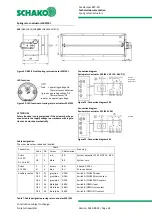
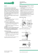
Flexible spigot type FS 


Figure 36: Flexible spigot type FS 


Ventilation  ducts  must  not  exert  significant  forces 
on walls, supports or ceilings and thus also on fire 
dampers as a result of thermal expansion (in case of 
fire). Appropriate compensation measures, such as 
the  arrangement  of  flexible  spigots  (SCHAKO  type 
FS) or a suitable duct routing (duct angles and dis-
tortions), must be taken as required. Alternatively, 
flexible ventilation ducts can be used. National reg-
ulations must be observed and adhered to. 


Flexible  spigot  consisting  of  profiled  connection 
flanges (made of galvanised sheet steel) with elastic 
intermediate  piece  made  of  polyester  fabric  PVC-
coated on both sides, standard flammable accord-
ing to EN 13501-1, with welded lip seals (sealing de-
gree  C  according  to  EN  13180/EN  1507;  tempera-
ture-resistant from -20° to +80°C). The flexible part 
of the spigot (polyester fabric) must have a length of 
L

min

 = 100 mm when mounted, resulting in an instal-

lation dimension of approx. L = 160 mm. This may 
reduce the free cross-section. 


The required equipotential bonding must be carried 
out  on-site  according  to  VDE  regulations.  The  fire 
dampers must not be subject to mechanical stress 
under any circumstances 


Extension piece type VT 


Figure 37: Extension piece type VT 


Extension piece made of profiled sheet steel fitted 
with connecting flanges 


Intended use: 
for large wall/ceiling thickness, in order to maintain 
a  minimum  distance  a

min


=  50  mm  from  the  open 

damper blade when fitting finishing protective grat-
ing type ASG, flexible spigot type FS or duct connec-
tion spigot type RS 


Duct connection spigot type RS 


The spigot diameter øD must be smaller then the smallest side di-
mension (width(B)/height(H)). Further dimensions are available 
upon request. 


Figure 38: Duct connection spigot type RS


Duct connection spigot with galvanised sheet steel 
joining plate 


Intended use: 
connection/transition from fire damper to round 
ventilation ducts 


B x H

øD

100x 100

98

150 x 100

98

150 x 150

148

200 x 150

148

200 x 200

198

250 x 200

198

250 x 250

248

300 x 250

248

Содержание BKP-EN

Страница 1: ...ndard EN 1366 2 PERFORMANCE DATA For automatic locking of fire lobbies For use or connection of a smoke release device with abZ e g SCHAKO smoke detection system RMS in connection with suitable releas...

Страница 2: ...tal posts 12 Lightweight partition walls with panelling on both sides and wall thickness W 100 mm 12 Wet installation of a fire damper complete mortar lining 12 Wet installation of a fire damper under...

Страница 3: ...sed on polyurethane varnish inside out side replaceable non coated parts are made of stainless steel material no 1 4301 Moulded connection flanges with centre hole or three equidistant holes on the B...

Страница 4: ...arranged at the points When using reveals the length of the drywall screws must be adjusted accordingly 15 Reveal optional on site 16 Solid ceiling 17 Mounting frame ER P1 accessories loose as mountin...

Страница 5: ...idth B 200 mm centre position for B 200 mm up to B 600 and 1 3 position for width 600 mm On the non operating side either fastening materials e g screws press in nuts etc must be provided and attached...

Страница 6: ...nelling on both sides 100 next to each other 200 EI 90 ve i o S 14 Wall 100 2 Ceiling 100 2 Wet installation in lightweight partition walls with metal posts and panelling on one side 115 next to each...

Страница 7: ...y have to be taken into consideration If a fire damper is not filled with mortar on all four sides installation and mounting aids on site must be removed Improper transport handling may result in dama...

Страница 8: ...nces to walls and ceilings and BKP EN to one another 1 Minimum distance recommended by SCHAKO for sufficient accessibility 2 The distance between the fire damper and the adjacent component wall ceilin...

Страница 9: ...ortar lining must be executed such that it is perma nent The information given by the mortar manufacturer must be observed INSTALLATION IN SOLID WALLS Installation in solid walls shaft walls shafts du...

Страница 10: ...and ceiling thickness D 125 mm Installation positions vertical suspended for large ceiling thicknesses vertical for large ceiling thicknesses suspended Figure 8 Installation positions in solid ceiling...

Страница 11: ...t be present in this area During the construction of the concrete base make sure that the housing of the fire damper is not pressed inwards reinforcement The minimum distance of fire dampers from one...

Страница 12: ...components are in creased by 25 mm Figure 13 Metal posts plus required exchange parts Mounting information In the overlap area of the exchangeable profiles they must be riveted crimped or screwed onc...

Страница 13: ...200 mm Average out the circumferential annular gap evenly between the wall and the BKP EN Mount the BKP EN with the help of mounting suspensions etc Insert mortar pos 13 into the circumferential annu...

Страница 14: ...e another must be at least 200 mm The minimum distance from adjacent components wall solid ceiling must be due to the construction at least 100 mm The actual minimum distance may slightly differ from...

Страница 15: ...ickness 100 mm for larger wall thicknesses the profiles must be adapted ac cordingly 11 Mineral wool according to the wall manufacturer s specifications 12 Panelling of the lightweight partition wall...

Страница 16: ...must remain mounted 10 1 Profile UW 75 40 0 6 150 profiles 12 1 Panelling on one side 2x20 of the shaft wall made of gypsum bonded wall boards 19 1 Drywall screws on site e g 3 5 x 35 mm 20 1 Reveal...

Страница 17: ...the help of mounting suspensions etc The fire damper is fastened to the supporting structure ex change profiles pos 10 1 on the B sides top and bottom using two fixing lugs each pos 18 4 per damper Th...

Страница 18: ...on in case of fire Appropriate compensation measures such as the arrangement of flexible spigots SCHAKO type FS or a suitable duct routing duct angles and distortions must be taken as required Nationa...

Страница 19: ...level without finishing protective grating Correction values B 100 mm with finishing protective grating type ASG LWA dB A x 1 08 p Pa x 1 4 Radiated noise LWA 6 dB A Application limits max operating...

Страница 20: ...m with finishing protective grating type ASG LWA dB A x 1 09 p Pa x 2 04 Radiated noise LWA 6 dB A Application limits max operating pressure of 1000 Pa at vface 10 m s Damper width B 250 mm Diagram 4...

Страница 21: ...m with finishing protective grating type ASG LWA dB A x 1 11 p Pa x 2 53 Radiated noise LWA 7 dB A Application limits max operating pressure of 1000 Pa at vface 10 m s Damper width B 400 mm Diagram 6...

Страница 22: ...m with finishing protective grating type ASG LWA dB A x 1 16 p Pa x 2 89 Radiated noise LWA 8 dB A Application limits max operating pressure of 1000 Pa at vface 10 m s Damper width B 600 mm Diagram 8...

Страница 23: ...with finishing protective grating type ASG LWA dB A x 1 14 p Pa x 2 92 Radiated noise LWA 8 dB A Application limits max operating pressure of 1000 Pa at vface 10 m s Damper width B 800 mm Diagram 10...

Страница 24: ...0 028 0 036 0 043 0 058 0 073 0 088 0 103 0 118 200 0 016 0 025 0 033 0 042 0 051 0 068 0 086 0 103 0 121 0 138 225 0 018 0 028 0 038 0 048 0 058 0 078 0 098 0 118 0 138 0 158 250 0 021 0 032 0 043 0...

Страница 25: ...ile made of sheet steel 2 Security grille type ASG 1 1 Standard design galvanised sheet steel material No 1 4301 and DD coating RAL 7035 light grey possible 2 Standard design galvanised sheet steel de...

Страница 26: ...ptionally 95 C respond Reaction of the ther mal fuses interrupts the supply voltage permanently Display of the damper end positions is possible by means of integrated micro switches via potential free...

Страница 27: ...W 0 8 1 1 Power consumption dimensioning 4 VA Imax 8 3 A 5 ms 6 5 VA Imax 4 A 5 ms Auxiliary switch 2 x EPU Switching capacity of auxiliary switch 1 mA 3 0 5 inductive A AC 250 V Connection of supply...

Страница 28: ...igure 33 Connection diagram S00 Connection diagram Spring return actuator S01 230V AC Figure 34 Connection diagram S01 The wires are colour coded and labelled Connection Cable Meaning Code No Colour A...

Страница 29: ...it and removing the ac tuator unit Pull duct tip internal duct temperature fuse off the temperature monitoring unit and replace it with a new duct tip with internal duct temperature of 72 C ASK79 4 or...

Страница 30: ...gger temperature duct inside temperature 72 C optionally 95 C for hot air heating Operating position damper OPEN and tensioning of the return spring by applying the supply voltage universal power supp...

Страница 31: ...of the spigot polyester fabric must have a length of Lmin 100 mm when mounted resulting in an instal lation dimension of approx L 160 mm This may reduce the free cross section The required equipotent...

Страница 32: ...mount ing frame type ER P1 Alternatively extension pieces on site or as accessories e g SCHAKO type VT can be mounted To avoid damage to components when mounting the mount ing frame type ER P1 the fir...

Страница 33: ...50 2010 Fire Damper Type version BKP EN Nominal conditions of activation sensitivity Load bearing capacity of the temperature sensitive measuring sensor Response temperature of the temperature sensiti...

Страница 34: ...digits 04 LENGTH 330 in mm always three digits 05 MATERIAL HOUSING SV Galvanised sheet steel V2 Stainless steel material no 1 4301 V2A 06 COATING HOUSING 0 Without coating 1 DD coating inside RAL7035...

Страница 35: ...ule mounted to BKP EN incl connection to drive unit without flat cable connection without addressing 32 EasyF AAC MASD 01 module mounted to BKP EN incl connection to drive unit with flat cable connect...

Страница 36: ...on one or both sides as classified according to EN 13501 2 or comparable national standards With concrete base on solid ceilings With installation frame type ER P1 in lightweight partition walls with...

Страница 37: ...n an installation dimension of approx L 160 mm The required equipotential bonding must be carried out on site according to VDE regulations The fire dampers must not be subject to mechanical stress und...

Страница 38: ...pivoting range of the damper blade and of the manual lever There is a significant risk of injury The fire damper must close and lock automatically lock ing of the damper blade in the CLOSED position 1...

Страница 39: ...or When the fusible link becomes damaged its replacement must be carried out as follows Replacement takes place by unscrewing both screws of the thermoelectric release device temperature moni toring u...

Страница 40: ...ries Release device The following functional steps have been carried out according to the documents installation mounting and operating instructions before commissioning next functional check in _____...

Страница 41: ...Web schako com Sample Functional check protocol for fire dampers Cons No ____________________ Defects found during the test on ________________________________________ Sluggishness due to soiling Any...

Страница 42: ...Luxembourg A 1060 Wien PL 05 500 Piaseczno Phone 352 403 157 1 Phone 352 403 157 1 Phone 43 1 890 24 62 Phone 48 22 7263570 Fax 352 403 157 66 Fax 352 403 157 66 Fax 43 1 890 24 62 50 Fax 48 22 72635...

Страница 43: ...Typ ES 25 Abbildung 28 Schaltbild Endschalter Typ ES Ex 25 Abbildung 29 BKP EN mit Federr cklaufantrieb B10 11 26 Abbildung 30 Anschluss Schema B10 B11 26 Abbildung 31 BKP EN mit Federr cklaufantrieb...

Отзывы: