Fire damper BKP-EN
Technical documentation
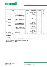
Installation in lightweight partition walls with metal posts
Construction subject to change.
No return possible!
Version: 2020-09-01 | Page 17
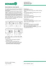
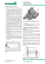
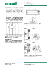
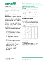
Figure 23: Detail fixing lugs
Installation procedure
Mount the metal posts and the wall in accordance with the
specifications of the wall manufacturer and the required ex-
change parts as shown on Figure 21. Leave a recess for in-
stalling the BKP-EN with mounting frame type ER-P1 (pos.
17).
Construct a circumferential reveal (pos 20.1) with 20 mm
plasterboards and screw them centrally to the circumferen-
tial metal profile frame (pos. 19.1 - fastening: e.g. drywall
screws ø 3.5 x 35 mm, screw distance ≤ 250 mm, but at least
2 screws per side).
Insert the BKP-EN into the wall recess, so that the stop of
the installation frame type ER-P1 contacts the wall (operat-
ing side – observe installation dimension of 200 mm up to
ER-P1 or 210 mm up to the front edge of the wall). Average
out the circumferential annular gap evenly between the re-
veal recess and the installation frame type ER-P1. Mount
the BKP-EN with the help of mounting suspensions, etc.
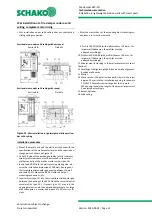
The fire damper is fastened to the supporting structure (ex-
change profiles - pos. 10.1) on the B sides (top and bottom)
using two fixing lugs each (pos. 18; 4 per damper). The fixing
lugs are fastened to the supporting structure using 2 drywall
screws for each lug (pos. 19.2, e.g. ø 5.5 x 90 mm).
Mounting aids (suspension, wedges, etc.) must be removed
(fixing lugs are no installation and mounting aids and must
remain mounted).
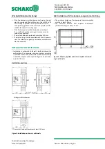
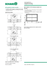
9.1 Profile CW 75/50/0.6 - 150 profiles
10.1 Profile UW 75/40/0.6 - 150 profiles
12.1 Panelling (on one side 2x20) of the shaft wall made of
gypsum-bonded wall boards.
16 Solid ceiling
17 Mounting frame ER-P1 (accessories: loose as mounting kit
or premounted ex works (extra charge)).
17.1 + 17.3 B side Parts 1 and 2
17.2 + 17.4 H side Parts 1 and 2
17.5 Countersunk head screw 4.0 x 60 mm (8 x)
18 Fixing lugs (accessories: mounting frame ER-P1)
19.1 Drywall screws (on site, e.g. ø 3.5 x 35 mm)
19.2 Drywall screws (on site, 2 x / fixing lug; e.g. ø 5.5 x 90 mm)
20.1 Reveal, circumferential (on site, 20 mm plasterboards)
37 Double-board layer (gypsum-bonded wall boards, d=20
mm, b=60 mm). Fastening: Dry-wall screws, for example,
ø 5.5 x 90, a ≤ 200 mm, but at least 2 screws per side,
connection and butt joints of the double-board layer
must be filled with the wall material.


