Fire damper BKP-EN
Technical documentation
Spring return actuators
Construction subject to change.
No return possible!
Version: 2020-09-01 | Page 29
Electric spring return actuator with temperature monitoring
unit
Trigger temperatures: room temperature 72 °C and inter-
nal duct temperature 72 °C optionally 95 °C (for hot air
heating).
Operating position (damper "OPEN") and tensioning of
the return spring by applying the supply voltage.
24V actuators with connectors that can be removed on
site if required.
Safety position (damper CLOSED) through spring force
when supply voltage is interrupted or the temperature
fuses (room temperature; 72 °C or internal duct tempera-
ture; 72 °C optionally 95 °C) respond. The response of the
thermal fuses interrupts the supply voltage permanently
and irrevocably.
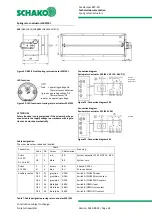
Display of the damper end positions is possible by means
of integrated auxiliary switches via potential-free
changeover contacts
(S1 - S3 CLOSED indicates the CLOSED position;
S4 - S6 OPEN indicates the OPEN position).
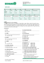
Technical data S00/S01
S00
(GRA126.1E/SO3)/
S01
(GRA326.1E/SO2)
Table 8: Technical data S00/S01
Manual actuation and fixing in any position is possible in
the de-energised state. It is unlocked manually.
An on-site functional check is possible by means of a
pushbutton or temperature monitoring unit permanently
connected to the actuator.
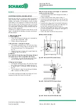
Spare parts: Duct tip for temperature monitoring unit
with internal duct temperature of 72 °C (ASK79.4) or 95 °C
(ASK79.5).
The replacement takes place by unscrewing both screws
at the temperature monitoring unit and removing the ac-
tuator unit. Pull duct tip (internal duct temperature fuse)
off the temperature monitoring unit and replace it with a
new duct tip with internal duct temperature of 72 °C
(ASK79.4) or 95 °C (ASK79.5). Reinsert temperature mon-
itoring unit into actuator unit and screw it down.
For damage other than to the duct tip (internal duct tem-
perature fuse), the entire actuator/temperature monitor-
ing unit set must be completely replaced.
Actuator type
S00
(GRA126.1E/SO3)
S01
(GRA326.1E/SO2)
Supply [V]
AC 24 / DC 24…48
(SELV/PELV)
AC 230
Operating voltage [V]
AC 24 ±20% /
DC 24…48 ±20%
AC 230 ±15%
Frequency [Hz]
50/60
Power consumption during operation
AC: 5 VA / 3.5 W
DC: 3.5 W
7 VA / 4.5 W
Power consumption in idle position
AC/DC: 2 W
3.5 W
Auxiliary switch
*)
Integrated, fixed switching point at 5° or 80°
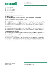
Auxiliary switch switching voltage [V]
AC 24…230 / DC 12…30
Auxiliary switch rated current [A]
AC: 6 (ohmic) or. 2 (inductive) / DC: 2
Supply cable
Cable 0.9 m, 2 x 0.75 mm² (halogen-free)
AC 24 V: (wires 1-2)/ AC 230 V: (wires 3-4)
+ 3-pin connector
Auxiliary switch cable (wires S1…S6)
Cable 0.9 m, 6 x 0.75 mm² (halogen-free)
+ 6-pin connector
Motor runtime (angle of rotation 90°) [s]
90
Spring return runtime [s]
15
Protection class
III according to EN 60 730
II according to EN 60 730
Degree of protection according to EN 60
529
IP54
Ambient temperature Normal operation
-32…+50 °C (actuator)
-20…+50 °C (temperature monitoring unit)
Storage temperature
-32…+50 °C (actuator)
-20…+50 °C (temperature monitoring unit)
Ambient humidity
<95% r.h. / no dewing (actuator)
CL D according to DIN 40040 (temperature monitoring
unit)
*) Either only mains voltage or only safety extra low voltage may be applied to the auxiliary switches. Mixed operation is not allowed. Operation with
different phases is not allowed.

