


Page 7/70
May 2015 I 2.0
1.
Components
1.1. Viper 4 terminal
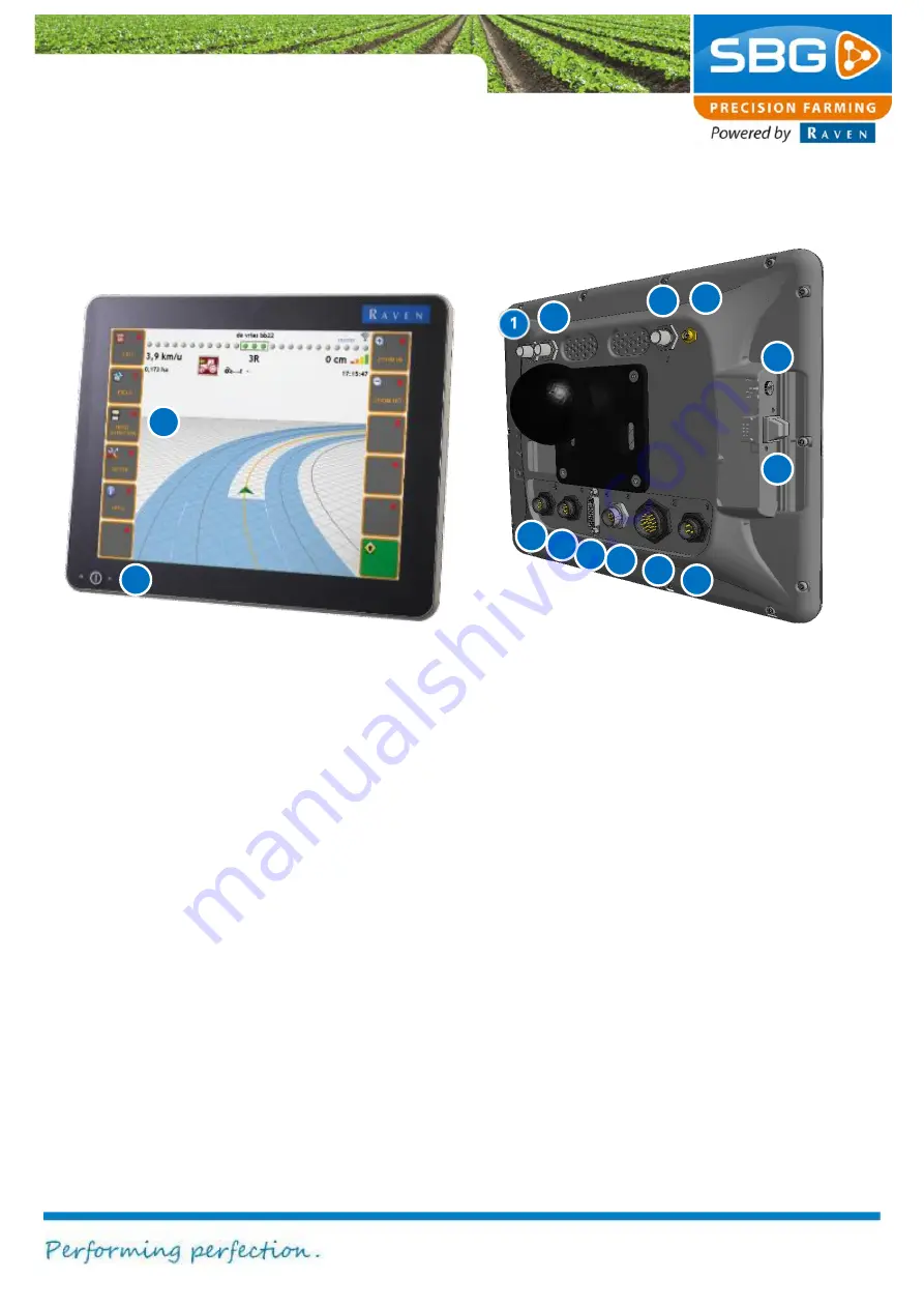
Figure 1 Viper 4 terminal
In Figure 1 all Viper 4 terminal connections are
numbered.
1. Radio (optional)
:
coax small (TNC)
2. GPS-antenna 2
: coax small (TNC).
Connection for the second GPS-antenna
(GPS2).
3. GPS-antenna 1
: coax small (TNC).
Connection for the main GPS-antenna
(GPS1).
4. WiFi-antenna
: FNC
5. External audio
:
3,5 mm jackplug
6. USB
:
2x
7. Power:
4-pin connector for 12V power.
8. Main interface
:
20-pins connector for
serial and CAN-bus communication.
9. Ethernet
:
8-pin network connector.
10. External display:
DVI.
11. CAN-bus:
additional CAN-bus connection.
12. Camera input
:
camera connection (not
supported in combination with
SBGuidance).
13. Touch-screen
: operations are performed
exclusively via a colour touch-screen.
14. Main power switch
2
3
4
5
6
7
8
9
10
11
12
13
14
Содержание GeoStar 200
Страница 1: ...USER MANUAL ENGLISH SBGuidance 4 0 0 Software operation...
Страница 14: ...System start up Page 14 70 May 2015 2 0 Intentionally left blank...
Страница 18: ...System start up Page 18 70 May 2015 2 0 Intentionally left blank...
Страница 54: ...Info Page 54 70 May 2015 2 0 Intentionally left blank...