22
RT-FS/RT-PHFS OWNER’S MANUAL
Requires:
Assembled 32" x 24" Phenolic Router Table and Hardware
Remaining Hardware from Floor Stand for Router Tables Hardware Pack
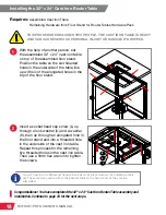
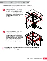
1
2
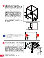
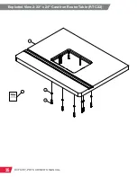
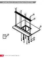
Set the assembled 32” x 24” phenolic
router table on top of the assembled
floor stand. Position the table so the
fourteen threaded holes in the underside
of the table line up with fourteen of the
elongated holes in the top of the
floor stand.
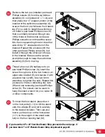
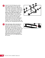
Insert a socket head cap screw (L) up
through a lock washer (U) and a
washer (K), then up through an
elongated hole in the floor stand and
into a threaded hole in the underside of
the phenolic table. Repeat this process
for the remaining thirteen threaded
holes in the phenolic table. Then use a
5 mm hex wrench to tighten the screws.
Installing the 32" x 24" Phenolic Router Table
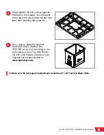
Congratulations! You have completed the 32" x 24" Phenolic Router Table assembly and
installation. Continue to the next page.
L
U
K


