background image

12

RT-FS/RT-PHFS OWNER’S MANUAL

5

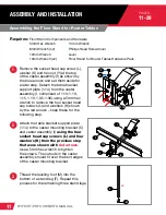
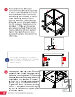
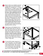
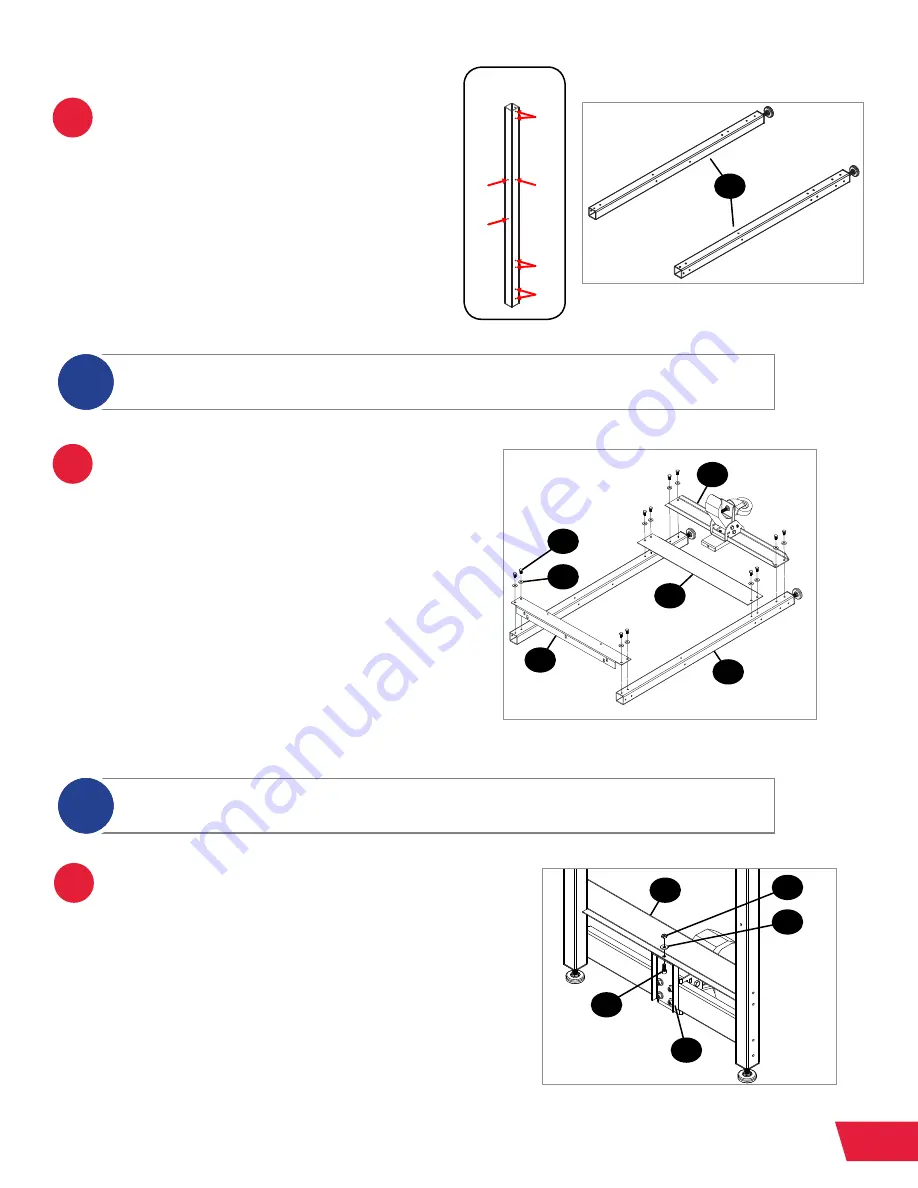
Refer to the hole pattern reference figure 
from step 4 and align the mounting 
holes in an upper side bracket (E) with 
the mounting holes in the stand legs (F) 
marked “aa,” align the mounting holes 
in a lower side bracket (B) with the holes 
marked “cc,” and align the mounting 
holes in the caster mounting bracket 
(C) with the holes marked “dd.” Mount 
the brackets to the stand legs (F) using 
twelve hex head bolts (V) and twelve 
washers (K). Set this assembly aside.

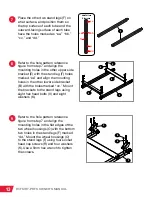
4

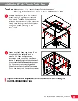
Place two stand legs (F) on a flat 
surface and position them so the top 
surface of each tube and the outward-
facing surface of each tube have the 
holes marked as “aa,” “bb,” “cc,” and 
“dd” in the hole pattern reference figure.

Only finger tighten the hex head bolts during assembly of the floor stand. You will tighten all 
the bolts after the stand is assembled.

i

The upper and lower side brackets are shorter than the upper and lower front/rear brackets. 
Make sure you are using the correct brackets for each step.

i

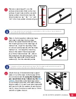
6

Attach the top of the table bracket support 
plate (1.14) to the bent, bottom edge of the 
lower side bracket (B) 

using the hardware 

you saved from step 1 shown by the 

blue


arrows

. Insert the socket head cap screw 

(L) up through the holes in the table bracket 
support plate (1.14) and lower side bracket (B) 
and secure it with the washer (K) and the hex 
nut (Y). Use a 5mm hex wrench and a 10 mm 
wrench to tighten the nut.

aa

bb

cc

dd

ee

ff

Hole Pattern

Reference

1.14

L

K

Y

B

E

B

C

F

V

K

F

Содержание RT-FS

Страница 1: ...OWNER S MANUAL STANDALONE ROUTER TABLE MODEL RT FS RT PHFS ...

Страница 2: ...Lock Downdraft Dust Collection Box for Router Lift Flip Stop for Router Fence and Single Vertical Feather Board for Router Tables are installed These are optional accessories that does not come included with your Standalone Router Table Your setup may look different SawStop the SawStop blade logo and the configuration of this product are either registered trademarks or trademarks of SawStop LLC So...

Страница 3: ...Standalone Router Table Assembly with Phenolic or Cast Iron Table and how to operate and maintain it Please read the manual carefully The manual also includes our warranty and important safety information If you ever have any questions or comments feel free to contact us at the address below SawStop LLC 11555 SW Myslony Street Tualatin Oregon 97062 USA Phone 503 570 3200 Fax 503 570 3303 Email inf...

Страница 4: ...HOW TO GET HELP Missing Parts Have Questions Our technical support team is standing by M F 6 30am 5pm PST to help with whatever you need 503 582 9934 Give us a call at SERVICE SAWSTOP COM Email us at ...

Страница 5: ...mbling the Fence Reference Warranty Safety Warnings Exploded View 1 Floor Stand for Router Tables RT STF Parts List 1 Floor Stand for Router Tables RT STF Exploded View 2 32 x 24 Cast Iron Router Table RT C32 Parts List 2 32 x 24 Cast Iron Router Table RT C32 Exploded View 3 32 x 24 Phenolic Router Table RT PH32 Parts List 3 32 x 24 Phenolic Router Table RT PH32 Exploded View 4 32 Fence Assembly f...

Страница 6: ...t Iron Table 32 x 24 Maximum Fence Travel 5 Front T slot to Arbor Center 6 Width of Front T slot at top 3 8 at bottom Rear T slot to Arbor Center 5 Width of Rear T slot 1 at top at bottom 32 x 24 Phenolic Router Table Phenolic Table 32 x 24 Maximum Fence Travel 30 Front T slot to Arbor Center 7 Width of Front T slot at top 3 8 at bottom Rear T slot to Arbor Center 5 Width of Rear T slot 1 at top a...

Страница 7: ...2 RT FS RT PHFS OWNER S MANUAL This page is intentionally blank ...

Страница 8: ...port Plate 1 Leveling Foot 4 Wheel Housing 2 3 Wheel 2 Pre Installed M5 x 0 8 x 45 Pan Head Phillips Screw 2 M6 x 16 x 2 Washer 1 M6 x 1 0 x 16 Socket Head Cap Screw 1 M10 x 1 5 Hex Nut 4 M6 x 1 0 Hex Nut 1 A B C D E F G I M O P H K L N Y Hardware Pack M8 x 1 25 Lock Nut 2 M6 x 16 x 2 Washer 55 M6 x 1 0 x 16 Socket Head Cap Screw 14 M8 x 1 25 x 50 Hex Head Bolt 2 M6 x 1 0 x 12 Socket Head Cap Scre...

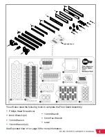
Страница 9: ...L M N O P Y HARDWARE PACK You will also need the following tools to complete the Floor Stand Assembly Phillips Head Screwdriver 8mm Wrench x2 10mm Wrench 13mm Wrench x2 See Exploded View 1 on page 33 for more information 14mm Wrench 5mm Hex Wrench Level ...

Страница 10: ...32 32 x 24 Cast Iron Table 1 M6 x 1 0 Hex Nut 10 M6 x 1 0 x 40 Flat Head Phillips Screw 10 A B C A B C You will also need the following tools to complete the Cast Iron Router Table assembly Phillips Head Screwdriver See Exploded View 2 on page 35 for more information ...

Страница 11: ... A B C 32 x 24 Phenolic Router Table 1 M6 x 1 0 Hex Nut 10 M6 x 1 0 x 40 Flat Head Phillips Screw 10 A B C You will also need the following tools to complete the Phenolic Router Table assembly Phillips Head Screwdriver See Exploded View 3 on page 37 for more information ...

Страница 12: ...Face Plate Space Bar 2 Router Fence Face Plate 2 Router Fence Guard 1 Router Fence Guard Spacer 2 32 Table Rail with Ruler and Lock Knob 2 Rail Mounting Bracket 2 1 4 x 20 x 5 8 Hex Head Bolt 6 M6 x 1 0 x 12 Socket Head Cap Screw 8 19mm Wide Lock Knob Nut 2 A B C D E F G H I J K L M N O P Q R S A B E F I O H G D C J L M N K P Q R S You will also need the following tools to complete the 32 Fence As...

Страница 13: ...ugh 4 The number after the decimal point refers to the part number as indicated by the number in the balloon in the exploded view For example a part referenced as 1 1 would be the part labeled with a 1 balloon in the exploded view 1 Exploded View 1 Floor Stand for Router Tables See page 33 Exploded View 2 32 x 24 Cast Iron Router Table See page 35 Exploded View 3 32 x 24 Phenolic Router Table See ...

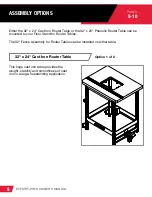
Страница 14: ...e 32 x 24 Cast Iron Router Table or the 32 x 24 Phenolic Router Table can be mounted to your Floor Stand for Router Tables The 32 Fence Assembly for Router Tables can be installed on either table This huge cast iron table provides the weight stability and smoothness of cast iron in a large freestanding application ...

Страница 15: ...10 RT FS RT PHFS OWNER S MANUAL 32 x 24 Phenolic Router Table Option 2 of 2 This huge phenolic table provides the lightweight precision of phenolic surfaces in a large freestanding application ...

Страница 16: ...ex wrench to remove the four socket head cap screws L and washers K shown by the red arrows keep these for the following step Attach the table bracket support plate 1 14 to the caster mounting bracket C and caster assembly I using the four socket head cap screws L and four washers K from the previous step that were shown with red arrows Use a 5mm hex wrench to tighten the screws The cutouts in the...

Страница 17: ...es marked as aa bb cc and dd in the hole pattern reference figure Only finger tighten the hex head bolts during assembly of the floor stand You will tighten all the bolts after the stand is assembled i The upper and lower side brackets are shorter than the upper and lower front rear brackets Make sure you are using the correct brackets for each step i 6 Attach the top of the table bracket support ...

Страница 18: ...rked aa and align the mounting holes in the other lower side bracket B with the holes marked cc Mount the brackets to the stand legs using eight hex head bolts V and eight washers K Refer to the hole pattern reference figure from step 7 and align the mounting holes in the flat edges of the two wheel housings O with the bottom two holes in the stand legs F marked dd Mount the wheel housings O to th...

Страница 19: ...ate the stand legs F upright so the leveling feet M are on the ground Refer to the hole pattern reference figure from step 7 and align the mounting holes in an upper front rear bracket D with the remaining top holes in two stand legs F marked as holes aa and align the mounting holes in a lower front rear bracket A with the holes in the stand legs F marked cc Mount the brackets D and A to the two s...

Страница 20: ...e bottoms of the stand legs F Make sure the feet are adjusted so the wheels P just contact the ground but can still spin relatively freely If the wheels P are not close enough to the ground the stand will not roll properly Insert a socket head cap screw R through a washer K then through the square hole in the handle mounting bracket T Then thread the screw into one of the single holes in the front...

Страница 21: ...s are tight enough to keep the switchbox assembly G from moving Thread a hex nut W halfway onto an pan head Phillips screw X insert the screw through one of the two holes in an upper side bracket E and secure it with a second hex nut W Use two 8 mm wrenches to tighten the nuts Repeat this process for the two remaining hex nuts W and one remaining pan head Phillips screw X The screws can be used to...

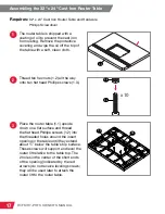
Страница 22: ...vel the router lift relative to the table top The 2 holes in the center of the short ends of the opening indicated by the red arrows do not receive leveling screws they will be used later to attach the router lift to the router table Assembling the 32 x 24 Cast Iron Router Table Requires 32 x 24 Cast Iron Router Table and Hardware Phillips Screwdriver 1 The router table is shipped with a coating o...

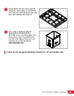
Страница 23: ...r Four Post Router Lift with Lock manual Copies of your manuals can be downloaded at www sawstop com 4 Finger tighten the hex nuts up against the bottom of the table You will adjust the screws and fully tighten the hex nuts later after installing the router lift Continue on to the next page for instructions to install the 32 x 24 Cast Iron Router Table ...

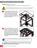
Страница 24: ... in the floor stand and into a threaded hole in the underside of the cast iron table Repeat this process for the remaining five threaded holes in the cast iron table Then use a 5mm hex wrench to tighten the screws Congratulations You have completed the 32 x 24 Cast Iron Router Table assembly and installation Continue to page 23 for the next steps Installing the 32 x 24 Cast Iron Router Table THIS ...

Страница 25: ... they extend about below the table s top surface These screws will support and level the router lift relative to the table top The 2 holes in the center of the short ends of the opening indicated by the red arrows do not receive leveling screws since they will be used later to attach the router lift to the router table Finger tighten the hex nuts up against the bottom of the table You will adjust ...

Страница 26: ... Dust Collection Box for Router Lift RT DCB do so now according to the instructions in your Four Post Router Lift with Lock manual Copies of your manuals can be downloaded at www sawstop com Continue on to the next page for instructions to install the 32 x 24 Phenolic Router Table ...

Страница 27: ...n of the elongated holes in the top of the floor stand Insert a socket head cap screw L up through a lock washer U and a washer K then up through an elongated hole in the floor stand and into a threaded hole in the underside of the phenolic table Repeat this process for the remaining thirteen threaded holes in the phenolic table Then use a 5 mm hex wrench to tighten the screws Installing the 32 x ...

Страница 28: ...2 into the T slot in a rail mounting bracket 4 20 Make sure the elongated holes in the rail mounting bracket 4 20 are on the top edge Use a 10mm wrench to tighten the hex head bolts 4 21 Place the rail and bracket on the side of your router table so the four holes in the rail mounting bracket align with the four threaded holes in the underside of the router table Use four socket head cap screws 4 ...

Страница 29: ...e sure the rear edge of the rail is flush with the rear edge of the router table Then use a 10mm wrench to tighten the hex head bolt 4 21 closest to the front of the rail Repeat this process at the back of the rail Recheck both ends then tighten the hex head bolt 4 21 in the center of the rail Repeat the previous step for the other rail attached to the other rail mounting bracket 7 The lock knobs ...

Страница 30: ...for the remaining five holes in the vertical portion of the router table fence Next you will assemble and install the 32 fence Thread a pan head Phillips screw 4 11 into one of the two holes on the side of the 2 dust port 4 10 then thread a square nut 4 12 partway onto the end of the screw Repeat this process with another pan head Phillips screw and square nut but thread the screw in the hole on t...

Страница 31: ...lates should cover the entire front of the router fence at this time 13 Tighten the six lock knobs 4 6 to secure the router fence face plates 4 14 To adjust the router fence face plates loosen the lock knobs on the back of the fence and slide the router fence face plates away from each other until they do not interfere with the router bit then retighten the lock knobs ALWAYS MAKE SURE THE LOCK KNO...

Страница 32: ...ightening the lock knobs Insert a T bolt 4 8 through a router fence guard spacer 4 16 with the square part of the spacer adjacent the head of the T bolt and the rounded part of the spacer facing away from the head of the T bolt Repeat this process with another T bolt 4 8 and another router fence guard spacer 4 16 Slide the router fence guard 4 15 onto the two T bolts so the rounded parts of the sp...

Страница 33: ...space bars onto the two T shaped extensions behind the fence face plate Then retighten the three lock knobs to secure the fence face plate in place 17 The next step is to attach the router table fence to the router table Insert a fence lock knob 4 2 through an M8 washer 4 3 then through one of the two elongated holes in the rear of the router table fence 4 1 and then thread a 19mm wide lock knob n...

Страница 34: ...2 dust hose to the router table fence to the dust port splitter on the dust box Further information can be found in your Four Post Router Lift with Lock manual which includes information about the dust box as well Copies of your manuals can be downloaded at www sawstop com Otherwise use a 2 dust hose not provided and two dust hose clamps not provided to attach the 2 dust port on the router table f...

Страница 35: ...located or have been used outside of the country where the authorized SawStop distributor from whom the Standalone Router Table system were purchased resides Please contact SawStop to take advantage of this warranty If SawStop determines the Standalone Router Table system is defective in material or workmanship and not due to misuse abuse negligence accidents normal wear and tear unauthorized repa...

Страница 36: ...o cause cancer and birth defects or other reproductive harm In addition some types of dust created by sawing power sanding grinding drilling and other construction activities also contain chemicals known to cause cancer birth defects or other reproductive harm Some examples of these chemicals are lead from lead based paints crystalline silica from bricks cement and other masonry products and arsen...

Страница 37: ... bit Never cut pieces between the fence and the router bit 14 Always ensure the router bit is in good working condition before use Examine the router bit prior to use and replace the bit if it is damaged 15 Ensure the Standalone Router Table and your router are installed securely before use 16 Maintain the Standalone Router Table as specified in this manual Use only identical replacement parts whe...

Страница 38: ...for the 32 cast iron router table which requires six sets of items 20 21 and 30 The configuration for the 32 phenolic router table requires 14 sets of items 20 21 and 30 20 30 21 9 7 8 1 31 20 20 21 14 21 3 11 10 12 13 17 16 18 19 22 23 2 34 20 5 6 1 4 20 30 21 20 31 32 26 28 25 28 27 20 17 28 33 32 5 31 20 2 29 27 20 4 36 37 15 35 24 ...

Страница 39: ...x 1 25 x 90 Hex Head Bolt RT STF 015 2 1 16 M8 x 18 x 2 Washer RT STF 016 2 1 17 M8 x 1 25 Lock Nut RT STF 017 4 1 18 3 8 16 Lock Nut RT STF 018 1 1 19 M10 x 19 x 2 Washer RT STF 019 1 1 20 M6 x 16 x 2 Washer RT STF 020 60 1 21 M6 x 1 0 x 16 Socket Head Cap Screw RT STF 021 19 1 22 Leveling Foot RT STF 022 4 1 23 M10 x 1 5 Hex Nut RT STF 023 4 1 24 Wheel Housing RT STF 024 2 1 25 3 Wheel RT STF 02...

Страница 40: ...35 RT FS RT PHFS OWNER S MANUAL Exploded View 2 32 x 24 Cast Iron Router Table RT C32 1 2 4 3 Standalone Router Table Owner s Manual ...

Страница 41: ...r Table RT C32 No Description Part No Qty N A Floor Stand Router Table Assembly RT C32 1 2 1 32 Router Table RT C32 001 1 2 2 M6 x 1 0 Hex Nut RT C32 002 10 2 3 M6 x 1 0 x 40 Flat Head Phillips Screw RT C32 003 10 2 4 Standalone Router Table Owner s Manual RT C32 004 1 ...

Страница 42: ...37 RT FS RT PHFS OWNER S MANUAL Exploded View 3 32 x 24 Phenolic Router Table RT PH32 1 2 3 6 5 4 Standalone Router Table Owner s Manual ...

Страница 43: ...ic Router Table Assembly RT PH32 1 3 1 32 Phenolic Router Table RT PH32 001 1 3 2 M6 x 1 0 Hex Nut RT PH32 002 10 3 3 M6 x 1 0 x 40 Flat Head Phillips Screw RT PH32 003 10 3 4 32 Phenolic Table Rail Insert RT PH32 004 1 3 5 M5 x 2 2 x 15 Flat Head Phillips Screw RT PH32 005 8 3 6 Standalone Router Table Owner s Manual RT PH32 006 1 ...

Страница 44: ...ssembly for Router Tables RT F32 2 3 1 4 24 5 14 8 18 19 12 22 17 8 16 15 7 6 21 7 23 20 6 7 10 11 12 9 13 14 3 2 18 18 19 12 22 21 7 23 20 4 for installation on 30 x 16 cast iron router tables 24 for installation on 32 x 24 phenolic or cast iron router tables ...

Страница 45: ... T Bolt RT F32 008 8 4 9 32 Router Table Fence Ruler RT F32 009 1 4 10 2 Dust Port RT F32 010 1 4 11 20 x Pan Head Phillips Screw RT F32 011 2 4 12 20 Square Nut RT F32 012 8 4 13 Face Plate Spacer Bar RT F32 013 2 4 14 Router Fence Face Plate RT F32 014 2 4 15 Router Fence Guard RT F32 015 1 4 16 Router Fence Guard Spacer RT F32 016 2 4 17 Spring Pin 3mm x 10mm RT F32 017 4 4 18 32 Table Rail RT ...

Страница 46: ...T VFS Holds your workpiece safely against the router fence for added stability Easy grip lock knobs Compatible with all SawStop Router Tables and Fences 9 Piece Brass Precision Template Guide Set RT TGS Includes 8 template guides for various routing applications 1 19 64 5 8 27 32 17 32 17 64 9 32 11 32 13 32 Includes 1 locking nut Includes 1 3 8 Insert Ring Designed to fit most routers Stock Guide...

Страница 47: ...for Router Fence RT FLS Designed to quickly give you accurate repeatable measurements Compatible with all SawStop Router Fences 4 Piece Phenolic Zero Clearance Insert Ring Set for Rout er Lift RT PZR Ultra strong phenolic core material to reduce tear out and chip out 4 Piece Phenolic Insert Ring Set for Router Lift RT PIR Ultra strong phenolic core material to reduce tear out and chip out ...

Страница 48: ...M RTR 19 0004 00 January 2018 SawStop LLC 11555 SW Myslony St Tualatin Oregon 97062 USA www sawstop com 503 570 3200 503 582 9934 503 570 3303 info sawstop com Main Phone Service Fax Email ...

Отзывы: