13
RT-FS/RT-PHFS OWNER’S MANUAL
7
8
9
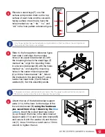
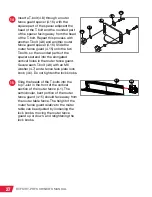
Place the other two stand legs (F) on
a flat surface, and position them so
the top surface of each tube and the
outward-facing surface of each tube
have the holes marked as “aa,” “bb,”
“cc,” and “dd.”
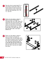
Refer to the hole pattern reference
figure from step 7 and align the
mounting holes in the other upper side
bracket (E) with the stand leg (F) holes
marked “aa” and align the mounting
holes in the other lower side bracket
(B) with the holes marked “cc.” Mount
the brackets to the stand legs using
eight hex head bolts (V) and eight
washers (K).
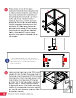
Refer to the hole pattern reference
figure from step 7 and align the
mounting holes in the flat edges of the
two wheel housings (O) with the bottom
two holes in the stand legs (F) marked
“dd.” Mount the wheel housings (O)
to the stand legs (F) using four socket
head cap screws (R) and four washers
(K). Use a 5mm hex wrench to tighten
the screws.
aa
bb
cc
dd
ee
ff
Hole Pattern
Reference
E
F
F
B
O
R
F
K
V
K

