


•
The chimney must have a constant cross section.
•
The flue must not be shared with any other appliance.
•
The chimney must be at least 4.5 m (15 ft high).
•
If the chimney has any downdraught tendency, due to
its position in relation to nearby obstacles, an
anti-downdraught cowl must be installed on the
chimney or the chimney height must be increased.
•
If the chimney draught is excessive or irregular, a
draught stabilizer (barometric damper) must be
installed to the connector pipe.
2.4.
Mounting the levelling feet
Figure 5, # 4
Fit the 4 screws and caps supplied on the burner into
each leg of the stove.
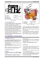
2.5.
Smoke exit
Figure 5 and 6
The rear exchanger is reversible (2 screws) so that the
smoke exit can be done at rear or on the top
2.6.
Chimney connector
•
The appliance must be as close as possible to the
chimney.
•
The connector pipe must be approved for installation
with combustion products (either 24 ga. Black painted
or blued steel or 316 grade 20 ga. Stainless steel or
1mm vitreous enamelled steel).
•
Pipe diameter must not be less than the appliance
spigot diameter.
•
The join between the connection pipe and the
stovepipe, and the flue, must be leak tight.
•
The connection pipe and any draught stabiliser must
have access for cleaning.
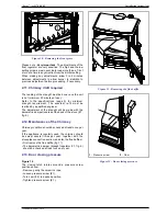
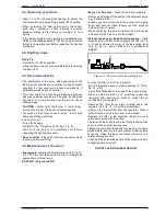
2.7.
Levelling
It is essential to ensure that the appliance sits level on
the floor.
-
Use a spirit level across the burner pot to check the
level (fig. 7).
Technical manual “1038”
5
“Savoy” - ref. 174 08 02
Installation instructions
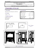
1
2
Figure 5 - Description
1
2
3
5
Figure 6 - Rear flue outlet
1
- Flue collar
2
- Blanking plate
3
- Draught regulator
4
- Control screws for
appliance leveling
5
- Flue baffle
6
- Burner
1
- Flue collar
2
- Blanking plate
Figure 7 - Burner level check


