
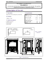


1.5. Operating principle
Heat is mainly diffused by radiation, through the window
and body of the appliance. The speed control is
obtained by control the oil flow into the burner.
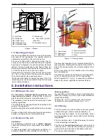
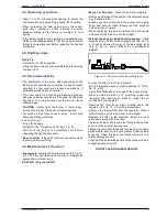
The stove is fitted with a vaporizing burner (fig. 3).
Furnace oil is fed to the burner floor where is it ignited
by means of a firestarter (or with an optional electrical
igniter). The heat produced by this flame brings the
burner temperature to the required level to vaporize the
oil. Oil will only burn as a vapour not a liquid.
Combustion air enters the burner through the air holes
(# 1, fig. 3). In the center of the burner is the catalyser
(# 2), which aids the the good combustion.
On the feed-line there is a de-scaling lever (# 5). The
de-scaling lever can be operated to keep the inlet pipe
clear of carbon buildup.
The stove float regulator (fig. 4) contains a filter (# F) to
trap impurities. A safety lever controls oil flow (# B). A
float in the chamber raises the oil level available to the
burner.
Oil can only enter the float chamber when the safety
lever is depressed.
The carburetor is also controlled by a control knob (# 2,
fig. 14, p. 8) which turns from “off" to ”high setting".
A draft regulator (# 1, fig. 9, p. 6) ensures a constant air
intake to the burner regardless of external factors.
2. Installation instructions
2.1. Warning to the user
An incorrectly installed heating appliance can
cause serious accidents
(chimney fires, burning of
plastic insulation materials, in partition walls, etc.).
The installation must be carried out according to local
building regulations.
The manufacturers responsibility shall be limited to the
supply of the equipment.
A remote acting fire valve must be fitted on the oil supply
line.
Flexible oil lines must not be used to make connections
between oil supply line and oil regulator valve.
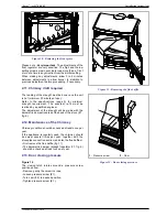
2.2. Position of the unit
Ventilation :
For satisfactory operation with a
natural draught,
check that sufficient air for combustion is available in
the room.
In houses equipped with mechanical ventilation, an
outside air intake must be installed for the chimney.
Chimney position :
For new chimney installations, select a central position
within the building, to provide a good heat distribution
around the building.
Position the unit to comply with the minimum
clearances to combustible material (fig. 1, p. 3).
2.3. Chimney
•
The flue must be in good condition and must provide
sufficient draught. (refer to technical details p. 3).
•
The flue must be suitable for the installation of fuel
burning appliances and comply with Current Building
Regulations.
•
The flue must be clean . It should be swept to remove
soot and dislodge tar deposits.
•
The flue must
be well insulated
, water and air tight. A
chimney with a cold internal surface can prevent a
good chimney draught and condensation will occur.
•
The flue must be watertight.
4
Technical manual “1038”
“Savoy” - ref. 174 08 02
Installation instructions
Figure 3 - Burner
Figure 4 - Float regulator
1
- Air holes
2
- Catalyser
2a
- Upper ring
2b
- Catalyser top
2c
- Catalyser body
3
- Burner pot
4
- Automatic ignition
(optional)
5
- De-scaling lever
A - Control knob
B - Safety lever
C - Main float
D -
Thermostat control
E - Oil level regulator
F - Filter
A
F
B
E
C
D


