1. Functional Description
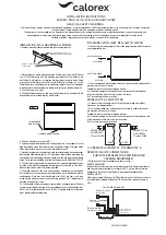
The breathing air purified in advance filters or, additional-
ly, in the belt unit is fed into the humidifier by the com-
pressed air supply hose (1). Upon streaming through
the humidifier's diaphragm module (3), the air becomes
automatically saturated with moisture. The purified and
humidified breathing air is ready to be supplied to a
full face or half mask respirator, by the outlet coupling
(11). While air is passing through the SATA breathing air
humidifier top air, there is no pressure drop, resp. no
remarkable air loss.
The water contained in the water storage (4) automati-
cally penetrates the diaphragm threads of the humidifier
module (3), always in a precisely sufficient quantity for
optimum saturation of the air. If there is no air stream
through the humidifier, water flow from outside to
inside is interrupted, and therefore droplet formation is
prevented.
2. Putting into Operation
When putting the unit into operation for the first
time, or after long breaks (several days), the water
storage (4) must be filled while being in a vertical
position until the maximum filling level (5), after
removing the closing screw of the filling opening.
After this, wait for 20 minutes to allow the diaphragm
threads to become saturated with water and reach
their maximum mechanical stability. In case the unit
is put into operation too early, without waiting time,
the diaphragm threads may be damaged, and water
may penetrate in an uncontrolled way into the air
passages. Always fill the SATA top air humidifier
while the unit is in vertical position. Upon reaching
the maximum filling level (5), insert and tighten again
closing screw of the filling opening.
After the 20 minutes' waiting time, connect the unit
to the belt unit by the air supply hose (1), while the
respirator is already coupled.
Attention:
The outlet coupling for respirator connec-
tion is no self-shut coupling, to avoid non-permissible
pressure rise inside the humidifier when the respirator
is disconnected. This means that in case the respirator
is disconnected, the entire air is freely released at the
coupling. Therefore always disconnect the humidifier
from the belt unit and air supply hose (1) first, and then,
if necessary, the respirator from the humidifier (the belt
unit features a self-shut coupling which automatically
interrupts the air stream).
Attention:
All couplings are safety couplings. Therefore
the nipple must be pressed tight into the coupling for
disconnection. Simultaneously the sleeve must be
shifted back.
Since the outlet coupling of the SATA top air is not self-
shutting, for reasons described above, always connect
respirator first to the humidifier, when putting the unit
into operation, before the appliance is connected to the
regulation valve / belt unit.
After this adjust, as usual, the required air volume at the
belt unit resp. regulation valve. No further steps need to
be taken at the humidifier itself.
Attention:
Never use the unit at a temperature of less
than +4°C, as damage may occur, resp. it may become
hard to breathe. While the unit is filled with water, never
expose it to frost - this may damage the unit.
3. Water Quality
To ensure sufficient life time of the humidifier module
and to obtain sufficient humidifying performance, use
distilled water exclusively.
Attention:
In no case anesthetic or similar materials may
be filled into the humidifier. This also applies for distilled
oils etc., since their effects in the breathing air may harm
the equipment wearer.
4. Safety Valve
The handle (8) features a built-in safety valve in order
to prevent destruction of the humidifier module by non-
permissible pressure rise. The safety valve in particular
helps to prevent uncontrolled pressure rise when the
breathing air hose leading to the respirator becomes
kinked. It is set to maximum 3 bars (43 psi) which is
never exceeded. This pressure is sufficient for the ope-
ration of all SATA respirators, and therefore for ensuring
maximum air supply.
Note:
If the safety valve is activated, check the air
pressure in the hose feeding the respirator, or the air
hose leading to the respirator for possible kinking. If
necessary, remove kinks, replace breathing air hose or
reduce air feed pressure.
1. Description de la fonction
L'air purifié par les filtres / l'unité de ceinture est mené,
à travers le tuyau (1), dans l'appareil. En passant le
module à membranes (3), l'air est saturé de mouillure et
sera donc à la disposition du peintre à l'accouplement
de sortie (11) où se branche le masque. Ce processus
n'entraîne pas de chute de pression / grande perte
d'air.
L'eau dans le récipient (4) va à travers les membranes
du module(3) seulement dans une quantité limitée suffi-
sante pour bien saturer l'air. S'il n'y a pas d'air passant
à travers l'appareil, le flux d'eau est interrompu, ce qui
empêche un rassemblement d'eau dans les parties
interdites.
2. Mise en marche
A la première mise en marche ou après une pause
de plusieurs jours, remplir le récipient (4) d'eau,
après avoir dévissé la vis de fermeture (9), en posi-
tion verticale jusqu'au niveau maximum (5). Après
cela, attendre environ 20 minutes pour permettre
aux membranes de se saturer afin d'atteindre leur
stabilité maximale. Si l'appareil est mis en marche
trop tôt, il y a le danger d'un endommagement
aux membranes, ce qui permettrait à l'eau de se
déplacer dans des parties réservées à l'air. Toujous
vérifier que le récipient est en position verticale pour
le remplissage. Après avoir atteint le niveau maxi-
mum (5), remettre et serrer la vis de fermeture.
Les 20 minutes d'attente passées, brancher
l'appareil à l'unité de ceinture, par le moyen du
tuyau d'air (1). Brancher le masque d'abord.
Attention:
L'accouplement pour le masque n'a pas
d'auto-fermeture, pour éviter une hausse non-con-
trôlée de la pression à l'intérieur de l'appareil au
débranchement du masque. C'est-à-dire qu'en cas le
masque est débranché, l'air entier quitte l'appareil à
l'accouplement.
C'est pourquoi il faut toujours débrancher d'abord
l'appareil de l'unité de ceinture et du tuyau d'air (1); et
puis le masque (si nécessaire). L'unité de ceinture pos-
sède un accouplement à auto-fermeture, interrompant
le flux d'air.
Attention:
Tous les accouplements sont des accouple-
ments de sécurité. Pour les enlever, pousser le nipple
fortement dans l'accouplement; et en même temps
retirer la manche.
Comme l'accouplement de sortie du SATA top air n'est
pas auto-fermant - pour des raisons décrites ci-dessus
- toujours brancher d'abord le masque à l'appareil à
chaque mise en marche, avant de brancher l'appareil à
la valve de réglage / unité de ceinture.
Après cela, ajuster comme d'habitude la quantité d'air
désirée à l'unité de ceinture / valve de réglage. Il n'est
pas nécessaire de faire des ajustages quelquonques à
l'humidificateur lui-même.
Attention:
Ne jamais utiliser l’appareil à une température
de moins de +4°C, car il risque d’être endommagé, resp.
la respiration pourra devenir difficile. Pendant qu’il est
rempli de l’eau, ne jamais exposer l’appareil à la gelée,
car cela l’endommagera.
3. Qualité de l'eau
Pour assurer une durée de vie suffisante du module
humidificateur et pour obtenir une performance suffisan-
te, utiliser exclusivement de l'eau déminéralisée.
Attention:
Ne jamais mettre des substances narco-
tiques (ou similaires) dans l'appareil. Cela s'applique
également pour les huiles essentielles car leur effet dans
l'air pourra mettre en danger le peintre.
4. Valve de sécurité
Le dispositif (8) contient une valve de sécurité afin
d'éviter la destruction du module humidificateur par une
hausse non-contrôlée de la pression. En particulier, la
valve de sécurité sert à empêcher une telle hausse en
cas le tuyau menant au raccord du masque est courbé.
La pression ne dépassera jamais 3 bars; car cette
pression est suffisante pour la fonction de tous les mas-
ques SATA et ainsi pour assurer un approvisionnement
maximum en air.
A noter:
Si la valve de sécurité devient active, vérifier
la pression amenée au masque, resp. le tuyau d'air
menant au masque pour des courbures. Si nécessaire,
enlever les courbures; remplacer le tuyau ou réduire la
pression d'air.
1. Funktionsbeschreibung
Die in entsprechenden Filtern, oder zusätzlich in der
Gurteinheit aufbereitete Atemluft wird über den Dru
ckluftzuführungsschlauch (1) in den Befeuchter ein-
geleitet. Beim Durchströmen des Membranmoduls
sättigt sich die Luft selbsttätig mit Feuchtigkeit. An
der Abgangskupplung (11) steht die aufbereitete und
befeuchtete Atemluft für den Atemanschluß z. B.
Atemschutzhaube oder Halbmaske usw. zur Verfügung.
Beim Druckdurchgang durch den Atemluftbefeuchter
SATA top air entsteht kein Druckabfall, bzw. kein nen-
nenswerter Druckverlust.
Das im Raum (4) befindliche Wasser dringt selbsttätig
durch die Membranfäden hindurch, und zwar nur soviel,
wie die Luft zur Sättigung aufnehmen kann. Strömt
durch den Befeuchter keine Luft, so ist der Wasserfluß
von außen nach innen unterbrochen.
2. Inbetriebnahme
Bei der ersten Inbetriebnahme oder bei der
Inbetriebnahme nach längeren mehrtägigen
Stillstandszeiten, ist der Wasserraum nach dem
Öffnen der Befüllschraube (9) bis zum maximalen
Füllstand zu befüllen. Danach das Gerät ca. 20
Minuten stehen lassen, damit die Membranfäden
sich mit dem Wasser sättigen können und ihre
mechanische Stabilität erreichen. Bei zu schneller
Inbetriebnahme könnten die Fäden beschädigt wer-
den. Die Befüllung des Befeuchters in senkrechter
Lage des Befeuchters vornehmen. Nach Erreichen
des maximalen Füllstandes die Befüllschraube wie-
der einsetzen und dicht einschrauben.
Nach der Ruhezeit von 20 Minuten das Gerät über
den Luftzuführungsschlauch (1) mit der Gurteinheit
bei vorher eingekuppeltem Atemanschluß verbin-
den.
Achtung:
Die Abgangskupplung für den Atemanschluß
ist keine selbstschließende Kupplung, damit zulässige
Druckanstiege in dem Befeuchter beim Abkuppeln
des Atemanschlusses nicht auftreten. Dies bedeutet,
wenn der Atemanschluß abgekuppelt wird, strömt die
gesamte Luft an der Kupplung frei ab. Deshalb den
Befeuchter immer zuerst an der Gurteinheit und dann
den Atemanschluß wenn nötig abkuppeln (an der
Gurteinheit ist eine selbstschließende Kupplung, die den
Luftdurchgang selbsttätig unterbricht).
Achtung:
Alle Kupplungen sind Sicherheitskupplungen.
Deshalb muß zum Entriegeln der Nippel tief in die
Kupplung eingedrückt werden. Gleichzeitig Schiebehülse
zurückschieben.
Da die Abgangskupplung am SATA top air aus dem
funktionsbeschriebenen Gründen nicht selbstschließend
ist, ist bei Inbetriebnahme der Atemanschluß immer
vor dem Ankuppeln des Luftzuführungsschlauchs des
Befeuchters an der Gurteinheit am Befeuchter anzu-
kuppeln.
Danach ist an der Gurteinheit, bzw. am Regelventil wie
gewohnt die gewünschte Luftmenge einzustellen. Am
Befeuchter selber sind keine weiteren Maßnahmen
notwendig.
Achtung:
Das Gerät darf nicht unter +4° C betrieben
werden, da das Gerät sonst Schaden nimmt bzw. das
Atmen erschwert wird. Wenn das Gerät mit Wasser
befüllt ist, darf es nie Frost ausgesetzt werden, sonst
besteht Beschädigungsgefahr.
3. Wasserqualität
Zur Sicherstellung einer ausreichenden Standzeit des
Befeuchtermoduls ist ausschließlich VE-Wasser zu ver-
wenden.
Achtung:
Auf keinen Fall dürfen narkotisierende
o.ä. Stoffe in den Befeuchter eingefüllt werden. Dies
gilt ebenso für ätherische Öle usw. da über den
Wirkmechanismus, bzw. über die Wirkungsweise keine
Aussage gemacht werden kann.
4. Überdrucksicherung
In den Halter (8) ist ein Überdruckventil eingebaut,
um eine Zerstörung des Befeuchtermoduls durch
eine unzulässige Druckbelastung zu verhindern. Das
Überdruckventil (10) dient dazu, z. B. den unzulässigen
Druckanstieg beim Abknicken des Atemluftschlauches
zum Atemanschluß zu verhindern. Es ist so eingestellt,
daß es bei 3 bar öffnet. Dieser Druck ist für den Betrieb
aller SATA Atemschutzgeräte ausreichend.
Warnhinweis:
Sollte das Überdruckventil ansprechen,
so ist der Zuführungsdruck zum Atemschutzgerät
zu überprüfen, bzw. ist der Atemluftschlauch zum
Atemschutzgerät auf Knickstellen zu untersu-
chen. Gegebenenfalls die Knickstellen beseitigen,
Atemluftschlauch austauschen, oder Versorgungsdruck
reduzieren.
SATA top air
Betriebsanleitung / Operating instructions / Mode d’emploi