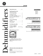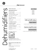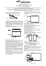


Use a Spirit level to check
that the bracket is horizontal
Holes to secure bracket
to the wall
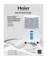
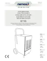
1. REMOVE FIXING SCREWS
2 HINGE COVER
AND LIFT AWAY
FIG 1
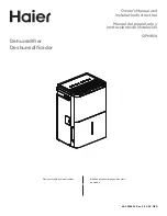
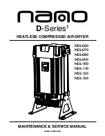
HEAT RECOVERED
WATER OUT
HEAT RECOVERED
WATER IN
DH33
DH55
WATER FLOW
AS SHOWN
15mm STUBS
WATER FLOW
AS SHOWN
15mm STUBS
100M MAX
1mm SQ CABLE
Remote Air Stat
(Not supplied)
Remote Humidistat
(Not supplied)
Remote On/Off
Switch
(Not supplied)
REMOTE THERMOSTAT
REMOTE HUMIDISTAT
REMOTE ON/OFF
FIG 2 WIRING DIAGRAM
HEALTH & SAFETY WARNING
As the Heat Pump contains electrical and rotational equipment, it is recommended that ONLY competent persons carry out any work on this type of machine
(see guarantee). Isolate electrically before entering machine or removing panels.
This appliance is not intended for use by persons (including children) with reduced physical,sensory or mental capabilities, or lack of experience and
knowledge, unless they have been given supervision or instruction concerning use of the appliance by a person responsible for their safety.
Children should be supervised to ensure that they do not play with the appliance
INSTALLATION INSTRUCTIONS
MODELS DH30/33/50/55/A/AX/ARH/AP/LPHW
INSTALLATION - WALL MOUNTING ALL MODELS
1. Remove machine from packaging and locate fixing bracket.
2. Place bracket on wall in required position. Drill one hole in the wall Ø 6.0mm
(no. 10) by 60mm deep. Use the wall plug provided to fix the bracket to the
wall. Using the bracket as a template mark positions for other holes. Using
a spirit level check that the bracket is level. Drill holes Ø 6.0mm (no. 10) by
60mm deep. Insert wall plugs and screw bracket in place. Note. The wall plugs
provided with the dehumidifier are suitable for fixing to a load bearing wall
3. Check all screws are tight.
4. The dehumidifiers are heavy and may require two or three people to lift the
dehumidifier on to locating lugs on wall bracket.
5. Remove front cover as shown FIG 1.
6. Locate pipe from drip tray and run it away to waste. A short length of 10mm
pipe is provided which should be led into a fixed waste pipe. Two pipe outlet
holes are provided, one to rear of unit, one below the unit.
7. Electrical supply to the unit must be sized according to data on serial number
label paying special attention to I.E.E. regulations latest edition regarding the
special conditions governing electrical supply to machines in potentially damp
areas. The machine should be installed in accordance with EMC2004/108/EC.
8. The electrical supply should be connected to the terminal block mounted on
the side of the bracket supporting the compressor. Brown/red to 'live', blue/
black to neutral and earth to the stud provided.
9. Fan mode switch can be set to cycle fan when humidistat senses demand
but should be set to continuous to promote good air circulation and reduce
condensation. Note that on models fitted with LPHW the fan(s) will start
automatically whenever there is an air heating demand. On 'X' models fan(s)
will stop during defrost cycle.
10. The humidity of the environment is controlled by a humidity sensor. The dial
for this is located on the bottom of the dehumidifier, on the left hand side for a
DH30/33 or the right hand side for a DH50/55. Turning the dial anti-clockwise
gives maximum dehumidification.
'RH' MODEL WITH HEAT RECLAIM TO WATER
11. Connect water circuit piping to 15mm stubs projecting from side of machine
as per diagram below:
12. It is recommended that isolating valves are fitted to enable isolation of the
machine in the event of service.
Complete water circuit as per diagrams overleaf.
(a) Circulating pump must be sized to take into account the design flow
rate of the machine plus the water system resistance.
For Pressure drops see data section.
MODELS WITH LPHW FITTED
13. Connect water circuit piping to 15mm stubs projecting from side of
machine as per diagram below:
14. It is recommended that isolating valves are fitted to enable isolation of
the machine in the event of service.
Complete water circuit as per diagrams overleaf.
(a) Circulating pump must be sized to take into account the design flow rate
of the machine plus the water system resistance.
For Pressure drops see data section.
12V REMOTE HUMIDISTAT, THERMOSTAT, &
REMOTE ON/OFF CONNECTIONS
(THESE OPTIONS NEEDS TO BE SPECIFIED WHEN
ORDERING DEHUMIDIFIER)
15. Remove cover from dehumidifier as shown in Fig 1.
REMOTE HUMIDISTAT
Remove link wire from mains in terminal block marked ‘Remote Humidistat
and connect remote humidistat as shown in FIG 2, ensure dial on internal
humidistat is set fully anti-clockwise (ie maximum dehumidifcation).
REMOTE ON/OFF
When connecting the Remote On/Off Switch remove the link from the mains
in terminal block marked Remote On/Off. Connect the switch as shown in
FIG 2.
SD139451 ISSUE 21