background image


SAS 1SF - Twin Screw Feeder Assy & Control - APRIL 2020 
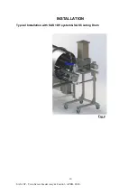
INSTALLATION 


During the installation there are combined actions of several operators, thus is 
necessary work with great caution.  
 
Verify the integrity of the machine, particularly of the fan covers over the electric motors 
that can be damaged during transport.  
 
If the fan covers are dented blocking the fan rotation, restore or replace them before 
commissioning the machine.  
 
When the screw feeder is provided without vertical unload and endless screw, with 
length of the screw exceeding the one of the exhaust pipe because of a customer 
request for installation needs, the customer is in charge of performing a risk analysis 
and of mounting proper protections and/or repairs.  
 
The operations performing the installation must have a technical grounding and proper 
knowledge to operate with adequate expertise.  
 
The user must have an installation area that satisfies the current regulations on health 
and safety on production environments.  
 
Set up an area where install the machine verifying that the floor is flattened and without 
obstacles.  
 
Make room around the machine sufficiently to permit safety and ergonomics to the 
operators and to the fitters. Safety distances from other machines or production areas 
must be observed according to the current regulations.  
 
The installation and working area must be correctly lit up, defined and signalled. It must 
respect the law parameters concerning working areas.  
 
The working area must be forbidden to personnel not involved in the machine 
operation. If this is not possible, barriers or similar means not hindering the production 
must be installed  


WARNING

The set-up of the machine is usually performed by the manufacturer 

who knows the right methods to do it. In case that the set up cannot be 
performed by the manufacturer, the customer has to ask the manufacturer all the 
information in order to perform it correctly by himself.  


Содержание 1SF

Страница 1: ...Feeder Assy Control APRIL 2020 SAS 1SF Twin Screw Feeder INSTRUCTION MANUAL Unit 3 Hawksworth Didcot OX11 7HR England UK Tel 00 44 1865 747 634 Fax 00 44 8701 602 755 info spiceapplications com www sp...

Страница 2: ...N 8 10 OPERATING PRINCIPLE 11 12 START UP 13 CLEANING 14 16 SERVICING 17 21 KEY COMPONENT REPLACEMENT 22 24 TROUBLESHOOTING 25 26 DECOMMISSIONING 27 SPARE PARTS 28 30 DIMENSIONS 31 32 TECHNICAL SPECIF...

Страница 3: ...f the equipment are forbidden to the unauthorized operators It is compulsory the grounding of the metallic box Any use of the equipment different from the intended one is strictly forbidden Read caref...

Страница 4: ...ne machine malfunctioning INAPPROPRIATE USE An inappropriate use of the machine may have serious risks for people and or the environment as well as causing damages to the equipment itself The equipmen...

Страница 5: ...SAFETY SIGNS During the normal cycle dangerous mobile elements are not reachable Operators are trained on possible critical situations and safety sign are positioned on the machine WARNING In case tha...

Страница 6: ...5 SAS 1SF Twin Screw Feeder Assy Control APRIL 2020 EC DECLARATION OF CONFORMITY FOR MACHINERY...

Страница 7: ...l flow high precision and dosing control together with integrated material agitation provided by an internal paddle SAS Part Number SAS 1SF BBL CC Description Part Number Reference BB Product Hopper 2...

Страница 8: ...SF 200 138 XXX See page 28 Fig 8 B Product Hopper Size 2 sizes SF 100 1XX See page 30 Fig 10 C Motor Gearbox Ratio 4 sizes See Table above on page 7 D Twin Screw Set 3 sizes SF 100 14X See page 29 Fi...

Страница 9: ...e user must have an installation area that satisfies the current regulations on health and safety on production environments Set up an area where install the machine verifying that the floor is flatte...

Страница 10: ...instructions TRANSPORTATION AND RECEIPT OF GOODS Check that during the transport any damage to the structure or internal parts of the equipment has not occurred Any damage must be immediately signalle...

Страница 11: ...10 SAS 1SF Twin Screw Feeder Assy Control APRIL 2020 INSTALLATION Typical Installation with SAS 1DV system SAS Coating Drum Fig 2...

Страница 12: ...umetric version It is expressed in dm h and the value is determined by the following factors o Dosing screw rotating speed o Dosing screw pitch and diameter length o Used product specific weight The m...

Страница 13: ...12 SAS 1SF Twin Screw Feeder Assy Control APRIL 2020 OPERATING PRINCIPLE...

Страница 14: ...e transport or the installation might damage or misadjust them Check the working temperature of the different components they do not have to overheat The first start up test must be done with the empt...

Страница 15: ...nitizing procedures during a change of processed product Particularly the motor group has no connection with the gears present on the screw feeder body Disassemble the machine following the operations...

Страница 16: ...er Not following this procedure can cause problems and void the warranty on the machine and on the components WARNING Never switch ON the electric power supply unit during the washing and cleaning ope...

Страница 17: ...ompletely with low pressure compressed air at 2 bar 29psi Wipe dry the equipment plus all hoses and cables carefully and thoroughly before commencing production THIS IS VERY IMPORTANT IF NOT DRY IT CA...

Страница 18: ...nt as well as turning on again the safety and protection devices after the maintenance has been completed The maintenance operations need a suitable equipped workshop The spare parts must always corre...

Страница 19: ...s must be carried out under the supervision of only one person At the end of the maintenance repairing operations the machine must be started up only after the OK of the supervisor who has to check th...

Страница 20: ...to open the inlet and outlet ports and the covers with the electrical power On WARNING It is absolutely forbidden to take off the safety guards during the equipment functioning Remove the safety guard...

Страница 21: ...ns about specific use of the machine please contact our technical office Extraordinary maintenance refers to repair and replacement operations of one or more machine Key components that are necessary...

Страница 22: ...ds solvents detergents corrosive liquids and abrasive materials for the machine cleaning It is not allowed the use of water jets directly on terminals electric panels or junction boxes WEEKLY CHECKS e...

Страница 23: ...e central fastening screw Fig 7 4 1 A 2 Loosen the shaft screws of the gear reducer from the housing Fig 7 4 1 A 3 Take the gear reducer off and replace it with the new one Follow the procedure in rev...

Страница 24: ...grub screws of the guide bearing present in the mixing paddle Fig 7 4 2 A 2 Loosen the break bridge agitating paddle always clockwise Fig 7 4 2 A ENDLESS SCREW REPLACEMENT To replace the endless scre...

Страница 25: ...and the frontal part and between the screw feeder body and the motors plate on the back To replace the gaskets perform the following actions 1 Take the frontal part of the screw feeder body off after...

Страница 26: ...he material 1 The gear reducer outlet shaft is faulty 1 Check the cause and then replace component 2 Wrong rotation direction 2 Change polarity 1 General checks Check that the screw conveyor starts wi...

Страница 27: ...voltage and the frequency directly from the terminal board of the electric engine Measure the rotation speed of the empty screw conveyor and compare the data with the one written on the engine plate...

Страница 28: ...is more or less long for example one month we suggest the following storage operations might be performed Unplug all the utilities electric and pneumatic Clean all the parts of the machine as describe...

Страница 29: ...4T Front Gasket Seal SF 100 144F Rear Gasket Seal SF 100 144R Mixing Paddle SF 100 145 Twin Screw sets See page 29 Fig 9 Please Note For Replacement Motor Gearboxes please contact SAS directly and pro...

Страница 30: ...SF 100 14X Fig 9 Position Part Number Description MC SF 100 142 High Flow Capacity Twin Screw Set EX Double pitch SF 100 141 Medium Flow Capacity Twin Screw set EX Single Pitch SF 100 140 Low Flow Ca...

Страница 31: ...er Assy Control APRIL 2020 SPARE PARTS POWDER HOPPERS Part Numbers SF 100 136 SF 100 143 50 Litre Hopper 20 Litre Hopper Part No SF 100 143 Part No SF 100 136 Fig 10 MOBILE STAND SCREW FEEDER Assembly...

Страница 32: ...NSIONS TWIN SCREW FEEDER MAIN BODY Assembly Number SF 200 138 XXX Fig 12 Model A B C D E F Weight Kg SAS 1SF 45x70 350 90 500 690 220 34 POWDER HOPPERS Part Numbers 100 136 100 143 50 Litre Hopper 20...

Страница 33: ...SF Twin Screw Feeder Assy Control APRIL 2020 DIMENSIONS TWIN SCREW FEEDER ASSEMBLIES Assembly Number SAS 1SF XXL SAS 1SF with 50L hopper SAS 1SF with 20L hopper Assy No SAS 1SF 50L Assy No SAS 1SF 20L...

Страница 34: ...r the use of materials that have very different granulometry and fluency They are available also in configuration for ATEX areas A screw feeder makes the function to unload a theoretically constant ma...

Страница 35: ...Load 2 8 up to 6 0 Amp Ratio dependant No of Drive Motors 2 x Motor Gearbox assemblies 1 x Twin Screw Motor Gearbox 0 25Kw up to 0 50Kw Ratio dependant 1 x Mixing Paddle Motor Gearbox 0 25Kw Protecti...

Страница 36: ...tems Ltd and good industry practice Spice Application Systems Ltd supplies all spare parts and consumable items Consumable spares are inspected frequently and replaced as necessary The life of these v...

Страница 37: ...36 SAS 1SF Twin Screw Feeder Assy Control APRIL 2020 Unit 3 Hawksworth Didcot OX11 7HR England UK Tel 00 44 1865 747 634 Fax 00 44 8701 602 755 info spiceapplications com www spiceapplications com...

Отзывы: