background image

2

A7408B

Smoke Detector Operation and Application

The closer/holder unit includes a 4-wire, photoelectric type smoke
detector. It provides: smoke detection, door holder solenoid control,
N.O. alarm contact, N.C. supervisory contact and interconnection to
other smoke detectors. Field option: one form C auxiliary contact (cut
jumper wire between 11 and 12).

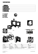
Terminal Inputs and Outputs

24VDC input power is applied to terminals 3 (-) and 14 (+) by the 
adjacent circuit board. Red LED flashes every 8 seconds

Terminals 1 and 2 provide a normally open (alarm) contact. This 
contact closes when smoke is detected. Red LED illuminates 
continuously

Terminals 5 and 13 provide a normally closed supervisory (trouble) 
contact. This contact opens when power is lost to the detector 
circuity. Red LED stops flashing

Terminals 9 and 6 provide rectified, unfiltered 24VDC to the door 
holder solenoid. This power is cut in alarm and the door closes

Terminals 7 and 8 provide rectified, unfiltered 24VDC to auxiliary 
devices when the detector alarms

Terminal 10 is rail + output. It is a continuous, rectified, unfiltered 
24VDC used for remote detector interconnect applications

Terminals 8, 9 and 10 may be field configured to a dry form contact
by cutting jumper between terminal 11 and 12. Terminal 10 is 
Common, 9 is N.C. and 8 is N.O. If this is done, Aux.+ is lost; 
solenoid power must be supplied by a separate source.

Terminals 15 and 4 provide interconnections to other detectors (See
diagram Pg. 4). Up to five smoke detectors may be interconnected. 
When a single detector alarms, terminal 15 goes high and any 
interconnected smoke detector will close its doors. The unit that 
initiated the alarm will have its LED on. The other interconnected 
units’ LEDs will flash as normal. Refer to interconnection wiring 
diagram for connections.

1

2

3

4

5

6

7

8

9

10

11

12

13

14

15

Detector Specifications (Part# 63-3210, Revision D)

Type: Photo-Electric Smoke Detector

Complies with UL 228 and UL 268 standards

Power Requirements:   24VDC +/- 10%

Nominal Sensitivity:  2.325 +/- 1.055%/FT

Contact Ratings

Alarm and/or Accessory

2.0 AMPS Max. @ 24VDC

(Resistive load)

0.6 AMPS Max. @ 120 VAC

Trouble Contact

0.5 AMPS Max. @ 24VDC

(Resistive load)

Connection List

Function

Terminal

24VDC input

3 (-), 14 (+)

Alarm contacts

1, 2

So

9

Solenoid -

6

Aux +

8

Aux -

7

Interc

15

Interconnect -

4

Trouble contacts

13, 5

+24VDC output (unfiltered) 10

NOTE: Terminals 4, 6 and 7 are same point.

Содержание 2900 Series FIREGUARD

Страница 1: ...ION TO PREVENT ELECTRICAL SHOCK AND EQUIPMENT DAMAGE 2 INSTALLER MUST BE A TRAINED EXPERIENCED SERVICE PERSON 3 ALL WIRING MUST COMPLY WITH APPLICABLE LOCAL ELECTRICAL CODES ORDINANCES AND REGULATIONS 4 MAXIMUM WIRE SIZE IS 18AWG Wiring 12 Units with and without 9 Companion Unit 9 Companion Unit If required Field wiring by others Wire nut On Off Test switch Yellow Red Black Yellow Black Black Term...

Страница 2: ... for remote detector interconnect applications Terminals 8 9 and 10 may be field configured to a dry form contact by cutting jumper between terminal 11 and 12 Terminal 10 is Common 9 is N C and 8 is N O If this is done Aux is lost solenoid power must be supplied by a separate source Terminals 15 and 4 provide interconnections to other detectors See diagram Pg 4 Up to five smoke detectors may be in...

Страница 3: ...a feature that detects when a smoke sensing chamber requires cleaning due to dirt and dust The need for cleaning is indicated by the flashing of the Red LED light once per second Normal Supervisory Operation Red LED flashes once every 8 seconds Dirty Chamber needs cleaning Red LED flashes once every second Smoke Detection Red LED is continuously illuminated To clean the smoke detector assembly fol...

Страница 4: ...5 4 10 Remote Detector N O C Relay 4 Use terminals 4 and 15 to wire detectors in parallel See 1 2 and 3 Use terminal 10 to signal remote detectors with relay contact only See 4 and 5 Five detectors maximum Accessory wire pack 63 3212 needed for unit interconnection ...

Страница 5: ...ousing by inserting crimped terminal end into housing body until crimped terminal snaps into position Use accessory wire pack 63 3212 15 Earth ground to track green wire 24VDC 0 15A Max to external alarm Power Supply Board 1 2 Alarm Circuit Trouble Circuit EOL RES Alarm Panel 24VDC Solenoid 24VDC 0 15A Max to external alarm 4 3 2 1 5 6 7 11 10 9 8 12 13 14 1 2 Power Supply Board 15 4 3 2 1 5 6 7 1...

Страница 6: ...ical data sheet Do not overload circuits 5 Wires are added to header housing by inserting crimped terminal end into housing body until crimped terminal snaps into position Use accessory wire pack 63 3212 15 24VDC 0 15A Max to external alarm bell horn etc Power Supply Board 1 2 24VDC Latch 4 3 2 1 5 6 7 11 10 9 8 12 13 14 Connect to power source 24VAC DC or 120VAC Power supply board and power sourc...

Страница 7: ...ay not reach the smoke detector and alarm it A detector may not detect a fire developing on another level of a building For this reason detectors should be located on every level of a building Smoke detectors have sensing limitations Photoelectric detectors sense smoldering fires better than flaming fires Ionization detectors offer a broad range of fire sensing capability but they are better at de...

Страница 8: ...oor stop Rotate cam until switch roller is on lower section of cam and approximately 1 32 from bottom of incline Cam should be positioned so when door closes roller on switch will ride up incline of cam operating the switch Tighten one set screw in cam with hex key and pull door closed 4 Pull door open to desired hold open position When switch roller travels down to bottom of incline door closer w...

Отзывы: