background image

A7408B

8

General Information

The 80 Prefix switch allows the initial hold open point to be adjustable from 20 degrees through full door opening.
This adjustment is done using a cam on the spindle opposite from where the arm mounts.
(Not available with 9- units.)

Adjustment Instructions

A. IMPORTANT

1. CAUTION: DISCONNECT ALL INPUT POWER BEFORE BEGINNING INSTALLATION TO PREVENT ELECTRICAL SHOCK AND

EQUIPMENT DAMAGE.

2. INSTALLER MUST BE A TRAINED, EXPERIENCED SERVICE PERSON.
3. ALL WIRING MUST COMPLY WITH APPLICABLE LOCAL ELECTRICAL CODES, ORDINANCES AND REGULATIONS.

B. Installation

1. Mount closer/holder per instruction sheet provided.
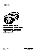
2. Locate switch and cam and loosen both set screws in cam.
3. Open door to desired holding position and hold open with door stop. Rotate cam until switch roller is on lower section of cam and

approximately 1/32" from bottom of incline. Cam should be positioned so when door closes, roller on switch will ride up incline
of cam operating the switch. Tighten one set screw in cam with hex key and pull door closed.

4. Pull door open to desired hold open position. When switch roller travels down to bottom of incline, door closer will function as a

standard multi-point holder. Depending on door size and closer fall back, cam may need to be adjusted so that the switch roller is 
positioned properly for desired door operation. Tighten both set screws firmly.

Cam

Set screw

Set screw

Approx. 1/32"

Switch
roller

Rotation of cam
when closing door

Rotation of cam
when opening door

Cam in Door Closed Position

Cam in Door Open Position

Top View of Closer/Holder

Set screw 2 places

Cam

Switch roller

SARGENT Optional 80- Prefix Bypass Hold Open Switch
for 2960, 2970 and 2990 Fire Guard

Содержание 2900 Series FIREGUARD

Страница 1: ...ION TO PREVENT ELECTRICAL SHOCK AND EQUIPMENT DAMAGE 2 INSTALLER MUST BE A TRAINED EXPERIENCED SERVICE PERSON 3 ALL WIRING MUST COMPLY WITH APPLICABLE LOCAL ELECTRICAL CODES ORDINANCES AND REGULATIONS 4 MAXIMUM WIRE SIZE IS 18AWG Wiring 12 Units with and without 9 Companion Unit 9 Companion Unit If required Field wiring by others Wire nut On Off Test switch Yellow Red Black Yellow Black Black Term...

Страница 2: ... for remote detector interconnect applications Terminals 8 9 and 10 may be field configured to a dry form contact by cutting jumper between terminal 11 and 12 Terminal 10 is Common 9 is N C and 8 is N O If this is done Aux is lost solenoid power must be supplied by a separate source Terminals 15 and 4 provide interconnections to other detectors See diagram Pg 4 Up to five smoke detectors may be in...

Страница 3: ...a feature that detects when a smoke sensing chamber requires cleaning due to dirt and dust The need for cleaning is indicated by the flashing of the Red LED light once per second Normal Supervisory Operation Red LED flashes once every 8 seconds Dirty Chamber needs cleaning Red LED flashes once every second Smoke Detection Red LED is continuously illuminated To clean the smoke detector assembly fol...

Страница 4: ...5 4 10 Remote Detector N O C Relay 4 Use terminals 4 and 15 to wire detectors in parallel See 1 2 and 3 Use terminal 10 to signal remote detectors with relay contact only See 4 and 5 Five detectors maximum Accessory wire pack 63 3212 needed for unit interconnection ...

Страница 5: ...ousing by inserting crimped terminal end into housing body until crimped terminal snaps into position Use accessory wire pack 63 3212 15 Earth ground to track green wire 24VDC 0 15A Max to external alarm Power Supply Board 1 2 Alarm Circuit Trouble Circuit EOL RES Alarm Panel 24VDC Solenoid 24VDC 0 15A Max to external alarm 4 3 2 1 5 6 7 11 10 9 8 12 13 14 1 2 Power Supply Board 15 4 3 2 1 5 6 7 1...

Страница 6: ...ical data sheet Do not overload circuits 5 Wires are added to header housing by inserting crimped terminal end into housing body until crimped terminal snaps into position Use accessory wire pack 63 3212 15 24VDC 0 15A Max to external alarm bell horn etc Power Supply Board 1 2 24VDC Latch 4 3 2 1 5 6 7 11 10 9 8 12 13 14 Connect to power source 24VAC DC or 120VAC Power supply board and power sourc...

Страница 7: ...ay not reach the smoke detector and alarm it A detector may not detect a fire developing on another level of a building For this reason detectors should be located on every level of a building Smoke detectors have sensing limitations Photoelectric detectors sense smoldering fires better than flaming fires Ionization detectors offer a broad range of fire sensing capability but they are better at de...

Страница 8: ...oor stop Rotate cam until switch roller is on lower section of cam and approximately 1 32 from bottom of incline Cam should be positioned so when door closes roller on switch will ride up incline of cam operating the switch Tighten one set screw in cam with hex key and pull door closed 4 Pull door open to desired hold open position When switch roller travels down to bottom of incline door closer w...

Отзывы: