Siemens FDM223, Technical Manual
The Siemens FDM223 Technical Manual is a comprehensive guide for operating and maintaining the product. This informative manual is available for free download from our website, ensuring quick and easy access to essential instructions and troubleshooting tips. Maximize the potential of your Siemens FDM223 with our user-friendly manual.
Share
Download


Reviews:
No comments
Related manuals for FDM223
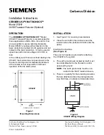
Cerberus Pyrotronics CP2297
Brand: Siemens Pages: 2

AnalogPLUS DB1131A
Brand: Siemens Pages: 6

Cerberus PRO FS720
Brand: Siemens Pages: 52
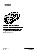
DBS721
Brand: Siemens Pages: 56

Cerberus CS1140
Brand: Siemens Pages: 250

DV1394A
Brand: Hawking Pages: 2

15220A
Brand: Faraday Pages: 66

DOW 1171
Brand: Bosch Pages: 31

SA5900-908
Brand: Apollo Pages: 2

GL09
Brand: Shanghai Wafer Microelectronics Pages: 6

NURIA
Brand: NIBBLE Pages: 26

CurrentLeak Whole Home
Brand: pivotal Pages: 2


