4
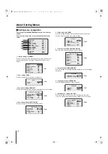
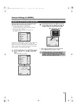
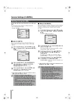
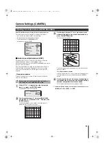
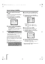
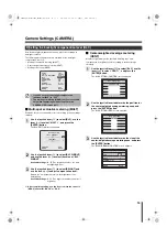
Before Using the Menu
1
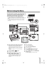
Make connections with all equipment and turn them on.
When the power is turned on, the camera will perform its
startup movements. The camera’s address and other
information will be displayed on the monitor screen. After the
startup movements have been completed, live image will be
displayed.
The main screen appears on the touch panel of the system
controller.
2
Press the [ADDRESS?
] button.
The address entering screen appears.
3
Enter the camera’s address using the 10 key
buttons, and press the [enter] button.
The address (camera number) entered here is the one
specified with the address setting switches (
A
) and is
displayed on the monitor screen during the startup
movements.
4
Press the [esc] button.
The main screen appears again.
5
Press the [TO SUB SCREEN] button.
The sub screen appears.
6
Press the [MENU] button in the sub screen.
The CAMERA MENU CONTROL screen appears.
7
Press the [MENU] button in the CAMERA MENU
CONTROL screen.
The camera menu appears on the monitor screen.
CAMERA
LENS
PAN/TILT
AUTO MODE
PASSWORD
LANGUAGE
OPTION
ADVANCED MENU
PRESET
MENU
SET
SET
SET
SET
SET
SET
SET
SET
OFF
END
y
y
y
y
y
y
y
y
esc
del
enter
1
2
3
4
5
6
7
8
.
0
9
1
?
D a t u m : 0 0 0 0 0
0 0 0 0 0
0 0 0 0 0
A c c e p t . v a l u e s
M a x 0 0 1 0 0
0 0 1 0 0
M i n 0 0 0 0 1
0 0 0 0 1
D i g i t
C a m e r a n r .
E s c t o e x i t
E s c t o e x i t
C A M 1 D V R 1
C A M 1 D V R 1
C A M 1 D V R 1
C A M 1 D V R 1
ALARM
PLAY
R PLAY
REC
ALARM
PLAY STOP
PLAY
SPEED
REC STOP
SEQ
ON
PAN
ON
TOUR
ON
SEQ/
PAN/
TOUR
OFF
ONE PUSH
AF
FOCUS
FAR
FOCUS
NEAR
IRIS
CENTER
GO TO
PRESET
TO SUB
SCREEN
SYSTEM
SETUP
MAP
ENTER
PLAY
SPEED
IRIS
IRIS
ADDRESS ?
DVR
MUX
ADDRESS ?
STILL
TIMER
ON/OFF
CLOCK
ADJUST
C A M 1 D V R 1
C A M 1 D V R 1
MENU
MENU
CODE
SEQUENCE
AUDIO
MENU
RESET
TO
10 KEY
MAIN
MONITOR
MON2
LOCK
UNLOCK
TO MAIN
SCREEN
ADDRESS ?
AWB
SET
AUX
ON
BLC
ON
ELS
ON
L-L
PHASE
L-L
PHASE
ELS
OFF
BLC
OFF
AUX
OFF
AWB
RESET
PRESET
MEMORY
ZOOM
PRESET
ON
ZOOM
PRESET
OFF
SEARCH
FR/FI
COPY
EXIT/OSD
ADDRESS ?
DVR
ZOOM
CHANNEL
MENU
ENTER
esc
C A M E R A M E N U C O N T R O L
C A M E R A M E N U C O N T R O L
E s c t o e x i t
E s c t o e x i t
C A M 2 D V R 1
C A M 2 D V R 1
1
2
3
4
5
6
7
8
ON
ON
OFF
1
2
3
4
5
6
ON
ON
OFF
A
B
3
1
2
5
3
7
4
6
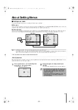
After installing the camera, use the menu to select camera operating options
and required functions according to your operating environment and
surveillance purpose. Use the system controller (VSP-9000) to perform menu
setting operations while viewing the menu on the monitor screen.
(The VAC-70, VSP-8500 also can be used to operate the camera.)
• To operate the system controller using the RS485 control method:
For system control setting switches (
B
), set the No.3 switch to the lower position
(OFF).
• To operate the system controller using the coaxial control method:
For system control setting switches (
B
), set the No.3 switch to the upper
position (ON).
When setting the address of the
camera, use numbers higher
than or equal to 1.
System controller
<Menu screen>
Monitor screen
<Main screen>
<Sub screen>
L5BW2_XE(VCC-MC800P_MC700P)(GB).book 4 ページ 2007年1月18日 木曜日 午前10時18分


