16
GB
7 - MAINTENANCE INSTRUCTIONS
7.1 - GENERAL MAINTENANCE
All equipment must be properly maintained in order to provide optimum performance over time. Faulty maintenance can result in
the cancellation of the product guaranty. Depending on the products, maintenance operations consist in the cleaning of filters (air,
water), internal and external exchangers, casings, and the cleaning and protection of condensate tanks. Treating odours and the
disinfection of room surfaces and volumes also contributes to the cleanliness of the air breathed by users.
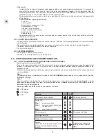
•
Carry out the following operations at least once a year
(the frequency depends on the installation and operating conditions):
- check for leaks on the refrigerating circuit (according to the order of 7th May 2007).
- check for traces of corrosion or oil stains around the refrigerating components,
- inspect the composition and the condition of the coolant and check that it does not contain traces of refrigerating fluid,
- cleaning the exchangers,
- checking the wear parts,
- checking the operating instructions and points,
- check the safety devices,
- de-dusting the electrical equipment cabinet,
- checking that the electrical connections are secure,
- checking the earth connection,
- check the hydraulic circuit (clean the filter, water quality, purge, flowrate, pressure, etc.).
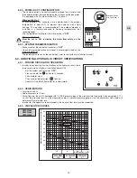
7.2 - HEATER SAFETY
• The unit's heater is equipped with an automatic-reset and a manual-reset safety thermostat.
• These thermostats trip in case of excessive temperature on the heater wall.
• Possible causes:
- Excessively low or inexistent water flowrate.
- Improperly purged water system.
• If the manual thermostat trips, correct the fault then reset the thermostat as follows:
-
Turn off and lock out the unit
.
- Remove the cover.
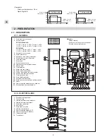
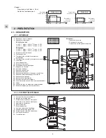
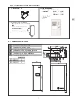
- The thermostats are located against the heater partition, on the front (see paragraph 2.1.1).
- Press the button in the centre of the manual thermostat.
7.3 - PROTECTION OF HEATER CIRCUITS
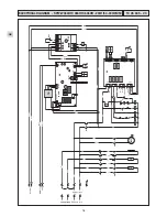
• The heater features three heating elements each supplied with 230 V between phases and neutral. Each of these circuits
are protected by a modular circuit breaker (
Q1, Q2, Q3
) located inside the electrical box.
7.4 - CONTROL CIRCUIT PROTECTION
• The indoor unit's control circuit is protected by a modular circuit breaker
Q4
located next to module
CC1
. It is accessible
through the small window on the right-hand side of the unit (without removing the cover panel).
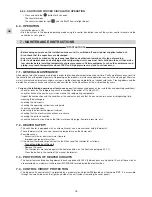
• Before doing any work on the installation, make sure it is switched off and all power supplies locked out.
• Also check that the capacitors are discharged.
• Any work must be carried out by personnel qualified and authorised to work on this type of machine.
• Prior to all maintenance and servicing on the refrigerating circuit, one must first shut down the unit then wait a
few minutes before installing temperature or pressure sensors. Certain equipment, such as the compressor and
piping, may reach temperatures above 100°C and high pressures may lead to serious burns.
IMPORTANT NOTE
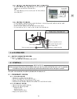
6.3.4 - SHUTDOWN FORCED CIRCULATOR OPERATION
• Press and hold the
button for 5 seconds.
The circulator stops.
The circulator indicator light
and the “
H
2
O
” flow rate light do out.
6.4 - OPERATION
• Installation power is ON.
• Start the system in the desired operating mode using the control box button (consult the system control manual and the
control box user's guide).
Содержание SPW-W366HH58
Страница 19: ...19 GB ...
Страница 37: ...19 FR ...
Страница 38: ...SANYO Airconditioners Europe S r l Via Bisceglie No 76 20152 Milano Italy SAN 10 11 525 GB FR 00 ...

