background image

Page 5

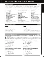
Transmitter
Model: MT-4 Telemetry System
Output Power: 100mW
Nominal Input Voltage: 4.8v ~ 7.4v
Operating Voltage Range: 4.0v ~ 9.6v
Dry Weight: 13.68oz (388gr)
Frequency: 2.4GHz FHSS-4T

Receiver
Model: RX-461 Telemetry
Frequency: 2.4GHz FHSS-4T
Nominal Input Voltage: 4.8v ~ 7.4v
Weight: 0.34oz (9.6gr)
Dimensions: 1.43 x 1.04 x 0.64in (36.2 x 26.5 x 16.3mm)
Fail Safe Limit: 

3.5v ~ 7.4v (FH4T) / 3.5v ~ 5.0v (FH2/FH3)

Torque:  80oz/in (5.8kg/cm @ 4.8v)


89oz/in (6.4kg/cm @ 6.0v)

Speed:  0.10 sec/60º @ 4.8v


0.08 sec/60º @ 6.0v

Dimensions:  1.59 x 0.83 x 1.04in


   (40.4 x 21.1 x 26.4mm)

Weight:  1.77oz (50gr)

Torque:  50oz/in (3.6kg/cm @ 4.8v)


61oz/in (4.4kg/cm @ 6.0v)

Speed:  0.17 sec/60º @ 4.8v


0.14 sec/60º @ 6.0v

Dimensions:  1.54 x 0.79 x 1.42in


   (39.1 x 20.0 x 36.0mm)

Weight:  1.55oz (43.9gr)

SDX-901 Digital High-Power Metal Gear Dual Ball Bearing Servo

Torque:  361oz/in (26.0kg/cm @ 4.8v)


423oz/in (30.5kg/cm @ 6.0v)

Speed:  0.19 sec/60º @ 4.8v


0.15 sec/60º @ 6.0v

Dimensions:  1.60 x 0.83 x 1.50in


   (40.6 x 21.1 x 38.1mm)

Weight:  2.33oz (66gr)

SDX-1322 Digital Standard Ball Bearing Servo

Both analog and digital servos will work with your 

MT-4 2.4GHz FHSS-4T

 radio control system. To get the most out of your 

experience, we recommend the use of digital servos in SHR or SSR mode. For more information about using different types 

of servos and the different Servo Mode Types, see the 

Changing the Mode Setting

 section on page 55. 

Torque:  124oz/in (8.9kg/cm @ 4.8v)


151oz/in (10.9kg/cm @ 6.0v)

Speed:  0.17 sec/60º @ 4.8v


0.13 sec/60º @ 6.0v

Dimensions:  1.54 x 0.78 x 1.50in


   (39.0 x 20.0 x 37.4mm)

Weight:  1.93oz (56gr)

SDX-772 Digital High-Power Metal Gear Dual Ball Bearing Servo

We recommend using SANWA brand servos with your 

MT-4 2.4GHz FHSS-4T

 radio control system. These are a few of our 

more popular servos.

  4-Channel 2.4GHz FHSS-4T Digital High-Response Computer Radio with Advanced Programming

  Telemetry System Features Updated Temperature, RPM/Speed and Voltage Displays in Real-Time on the Telemetry Screen

  

High-Power FHSS-4T Technology Provides the Best Reception and Connectivity, Giving Racers Added Assurance

  4-Cell Battery Holder for Lighter Weight - Also Accepts Optional Ni-Cd/MH Batteries or 2S Li-Po or 2S Li-Fe/A123 Battery Packs

  Adjustable Grip

  Variable Rate Adjustment

  Model Naming

  Model Select

  Model Select Shortcut (Direct Model)

  Model Clear

  Selectable Modulation Type

  Multi-Function LCD Contrast

  Adjustable Key Volume and Tone

  Programmable Low Voltage Alarm

  Inactivity and Over Voltage Alarms

  Digital Battery Voltage Monitor

  18 Model Memory

  Telemetry Logging

  Channel Set Menu

  Servo Reversing

  Steering, Throttle and Brake Dual Rate

  End Point Adjustment 

  Exponential and ARC Adjustment

  Servo Speed Adjustment

  Anti-Lock Braking

  Throttle Offset

  Lap and Interval Timers

  Total, Best and Individual Lap Display

  Four Wheel Steering Mixing

  Dual Throttle Mixing w/Dig & Burn 

 

Normal, SSR and SHR Servo Modes

  Center or Parallel Trim Types

  Step Auxiliary

  Point Auxiliary

  Auxiliary Mixing

  Programmable Fail Safe

  Receiver Battery Voltage Fail Safe

  Digital Trims

  Servo Sub-Trim

  Adjustable Throttle Trigger

  Programmable Switches, Lever and Dial

  Adjustable Steering Wheel

GENERAL

FEATURES AND SPECIFICATIONS

SYSTEM FEATURES

SYSTEM SPECIFICATIONS

SERVO RECOMMANDATIONS

SDX-801 Digital High Metal Gear Low-Profile Dual Ball Bearing Servo

Содержание MT-4

Страница 1: ...OPERATING MANUAL ...

Страница 2: ...9 Transmitter Safety Alarms and LED Condition Indicators Page 9 System Connections Page 11 Transmitter Battery Options Page 11 Alkaline Battery Installation Page 11 Transmitter Battery Charging Options Page 11 Warnings if Using Li Po or Li Fe A123 Transmitter Batteries Page 11 Receiver Connections and Mounting Page 12 Telemetry Connections and Mounting Page 13 Adjustments and Options Page 14 Throt...

Страница 3: ...t the help of a fellow modeler to walk the model to the farthest reaches of the track or for boats to walk the shore line well in excess of the operational distance of the boat then test for proper operation This radio control system operates on the 2 4GHz frequency band The 2 4GHz connection is determined by the transmitter and receiver pair Unlike ordinary crystal based systems your model can be...

Страница 4: ...arrying handle during use Doing so can block the RF signal resulting in the loss of control of your model During use hold the transmitter so that the antenna is orientated as close to vertical as possible at all times This provides the best RF signal between the transmitter and the receiver You should never point the antenna directly at your model nor should you ever follow your model with the ant...

Страница 5: ...DX 772 Digital High Power Metal Gear Dual Ball Bearing Servo We recommend using SANWA brand servos with your MT 4 2 4GHz FHSS 4T radio control system These are a few of our more popular servos 4 Channel 2 4GHz FHSS 4T Digital High Response Computer Radio with Advanced Programming Telemetry System Features Updated Temperature RPM Speed and Voltage Displays in Real Time on the Telemetry Screen High ...

Страница 6: ...r antenna is mounted internally and is located in the vertical back portion of the carrying handle When you re driving your model hold the transmitter so that the antenna is orientated as close to vertical as possible at all times This provides the best RF signal between the transmitter and the receiver You should never point the antenna directly at your model nor should you ever follow your model...

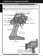
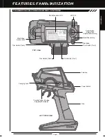
Страница 7: ... Multi Function LCD LED 1 2 Push Button Rotary Dial Up Down Enter Key Back Cancel Key Dial Knob top view Trim Switch Trm1 Trim Switch Trm2 Trim Switch Trm3 Trim Switch Trm4 Wrist Strap Anchor Slot Charging Jack LEFT Side view Throttle Trigger Position Adjustment Indicator Power Switch Antenna Grip GENERAL ...

Страница 8: ...arge Alkaline batteries If using an after market Peak Detection charger or other type of fast charger the batteries should be removed from the transmitter to avoid damage to the transmitter circuitry and or your batteries Do not attempt to charge a Li Po or Li Fe A123 battery pack through the Charging Jack Coaxial Cable The portion of the receiver antenna that extends the Antenna Reception Wire Th...

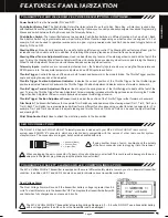
Страница 9: ...user Turning the Throttle Trigger Tension Adjustment Screw clockwise increases throttle trigger tension and turning the Throttle Trigger Tension Adjustment Screw counter clockwise decreases throttle trigger tension Throttle Trigger Position Adjustment Screw Used to adjust the position of the Throttle Trigger either forward or backward Trim Switch The transmitter features four separate Trim Switche...

Страница 10: ... Output Signal OK Throttle Offset Value ON with Positive or Negative Value Programmed Telemetry Logger Function Operating Anti Lock Braking Function Operating No Transmitter Receiver Telemetry Connection Telemetry Alarm Started Low Voltage Alert Alarm Started Bind Command Transmitted Inactivity Power ON Alarm Started Low Voltage Limit Alarm Started Over Voltage Alarm Started LED COLOR LED CONDITIO...

Страница 11: ...the Warnings if Using Li Po or Li Fe A123 Batteries section below GENERAL SYSTEM CONNECTIONS TRANSMITTER BATTERY OPTIONS ALKALINE BATTERY INSTALLATION In the default configuration the transmitter is designed to be powered using four AA Alkaline batteries This results in of the transmitter by pushing firmly on the Slide the battery cover back onto the transmitter and push it firmly until it clicks ...

Страница 12: ... torque and speed provided by using 7 4 volt digital servos Only use a 2 cell Li Po or 2 cell Li Fe A123 battery pack if your servos are rated to handle the higher voltage If you re using an Electronic Speed Control with BEC circuitry verify that it reduces the voltage to between 4 8 and 7 4 volts before making your connections and turning your radio control system ON Switch AA Dry Cell Battery Ho...

Страница 13: ...you want to monitor Mounting the RPM Sensor The RPM Sensor uses infrared technology to record RPM data from a rotating part included that is attached to the rotating part so that the RPM Sensor can see it as it passes in front of the Sensor Pickup Install the RPM Sensor into your model making sure that it s held securely in place For optimal operation the Sensor Sensor End Input Plug Do not try to...

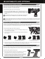
Страница 14: ...ngled toward the right or left It all depends on your personal preference Throttle trigger adjustment plates are included to fine tune the angle A B Throttle Trigger angle adjustment To adjust the throttle trigger angle follow the steps below 1 Use a 1 philips head screwdriver to remove the throttle trigger mounting screw A from the left side of the transmitter 2 Use the tip of a modeling knife to...

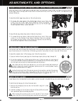
Страница 15: ...teering wheel firmer use a 1 5mm hex wrench to turn the Steering Wheel Tension Adjustment Screw A clockwise To decrease the spring tension of the steering wheel looser turn the Steering Wheel Tension Adjustment Screw counter clockwise A adjustments and options The spring tension of the throttle trigger and steering wheel can be adjusted to best suit the user Some users may prefer the throttle trig...

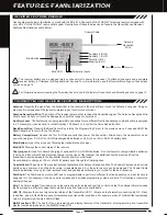
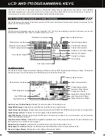
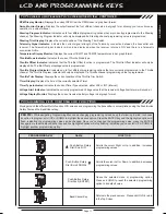
Страница 16: ...s RPM Temperature and Receiver Voltage To display the Telemetry Screen from the Top Screen scroll DOWN using the Push Button Rotary Dial Auxiliary Lever Position Display Displays the current position of the Auxiliary Lever Digital RPM Display Displays the current RPM from the RPM Sensor in digital format Digital Temperature Display Displays the current temperature from the TEMP1 and TEMP2 Temperat...

Страница 17: ...yed when the receiver is turned ON and there is a Telemetry connection Active Temperature Display Monitor Displays the current TEMP1 and TEMP2 temperatures in bar graph format Throttle Mode Indicator Indicates the current Throttle Mode type Throttle Offset Indicator Indicates that the Throttle Offset function is programmed The Throttle Offset Indicator will only be displayed if a Throttle Offset p...

Страница 18: ...he BIND menu When the Binding procedure is successful the Bind LED on the receiver and LED 1 on the transmitter will illuminate solid In this case turn both the transmitter and receiver OFF then repeat the Binding procedure again 4 5 After the Bind LED on the receiver goes out press the ENTER key a second time The Bind LED on the receiver will illuminate solid blue and LED 2 on the transmitter wil...

Страница 19: ...g System Menu Change Common Programming Options in One Convenient Location Adjust Channel Dual Rates Adjust Channel End Points Adjust Channel Exponential or Adjustable Rate Control ARC Slow Down Servo Speed in the Forward and Return to Neutral Directions Program the Anti Lock Braking Function Program the Throttle Offset Position Choose and Adjust Auxiliary 1 Channel 3 Functions and Programming Cho...

Страница 20: ... NOR REV 19 F S 01 EPA HIGH 02 EPA LOW 03 CURVE RATE 04 CURVE POINT 05 CURVE 06 CURVE 07 SPEED FORWARD 08 SPEED RETURN 09 TRIM 10 SUB T 11 REV NOR REV 12 F S 01 EPA HIGH 02 EPA LOW 03 CURVE RATE 04 CURVE POINT 05 CURVE 06 CURVE 07 SPEED FORWARD 08 SPEED RETURN 09 TRIM 10 SUB T 11 REV NOR REV 12 F S ST STEERING TH THROTTLE A1 AUXILIARY 1 A1 AUXILIARY 2 The following Programming Menus are available ...

Страница 21: ...vo travel is increased D R TH RATE setting range is 0 to 100 The default setting is 100 Adjusting the Brake Dual Rate Percentage Value 1 From within the D R menu scroll UP or DOWN to highlight BR RATE 100 2 Press the ENTER key then scroll UP or DOWN to increase or decrease the Brake Dual Rate percentage value When the Brake Dual Rate percentage value is decreased Throttle Brake side servo travel i...

Страница 22: ...n see the Adjusting the Servo Sub Trim Values section on page 42 Adjusting the Steering End Point Adjustment Percentage Values Your model s turning radius can differ from left to right because of variations in linkage suspension balance tire diameter or weight distribution In such cases Left Steering servo travel and Right Steering servo travel are adjustable using the End Point Adjustment functio...

Страница 23: ...vo travel are adjustable using the End Point Adjustment function 1 From within the EPA menu scroll UP or DOWN to highlight A1 EPA H 100 or A2 EPA H 100 2 Press the ENTER key then scroll UP or DOWN to increase or decrease the Auxiliary High End Point Adjustment percentage value Increasing the percentage value will increase auxiliary servo travel in that direction and decreasing the percentage value...

Страница 24: ...the Exponential Rate percentage value is programmed from a fixed Neutral Point of 50 and the Adjustable Rate Control Rate percentage value is programmed from a user adjustable Neutral Point giving you even greater programming control 1 From the Top Screen press the ENTER key to open the Programming Menu list 2 Scroll UP or DOWN to highlight the CURVE menu then press the ENTER key The CURVE menu wi...

Страница 25: ...u to see your programming changes in virtual real time Adjusting the Point Percentage Value The Point percentage value determines the Neutral Point where the Rate percentage value begins For example you may not want the Point to be centered between the High and Low End Points You may want the Point to be offset from the center position The Point percentage value option is available ONLY when the T...

Страница 26: ...cause the servo transit time to slow down when it moves from either End Point to the Neutral position SPEED RETURN setting range is 100 to 0 The default setting is 0 Normal Speed Adjusting the Forward Speed Value 1 From the Top Screen press the ENTER key to open the Programming Menu list 2 Scroll UP or DOWN to highlight the SPEED menu then press the ENTER key The SPEED menu will be displayed and S...

Страница 27: ...k Braking function to operate 3 Press the ENTER key then scroll UP or DOWN to increase or decrease the Stroke percentage value Increasing the Stroke percentage value will increase throttle servo travel in the Brake direction and decreasing the Stroke percentage value will decrease throttle servo travel in the Brake direction ALB STROKE setting range is OFF to 100 The default setting is OFF Adjusti...

Страница 28: ...ase value will cause the Brake to move from Neutral to the Stroke setting faster ALB RELEASE setting range is 0 01s to 1 00s The default setting is 0 03s 2 From within the ALB menu scroll DOWN to highlight HOLD 0 03s Press the ENTER key then scroll UP or DOWN to increase or decrease the Hold value Increasing the Hold value will cause the Brake to move from the Stroke setting to the Neutral positio...

Страница 29: ...g Options Controls Dual Throttle Options Controls User Defined Auxiliary 1 Channel 3 Mixing Options IMPORTANT Prior to programming an Auxiliary 1 Programming function you must first choose the desired Auxiliary Programming function in the SYSTEM AUX TYPE menu Only one Auxiliary 1 Programming function can be Active at any given time The Step Auxiliary function allows you to program the Auxiliary 1 ...

Страница 30: ...ction Choosing the Step Auxiliary Function 1 From the Top Screen press the ENTER key to open the Programming Menu list Use one of the four Trim Switches or the Rotary Dial to cycle through the Point positions while you re driving The Point Auxiliary function can be toggled OFF and ON while you re driving by assigning Auxiliary 1 to one of the two Push Button Switches 2 Scroll UP or DOWN to highlig...

Отзывы: