Page 8
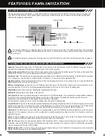
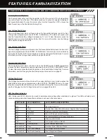
Use the diagram below to familiarize yourself with the RX-461 4-Channel 2.4GHz FHSS-4T Telemetry receiver included with
your
MT-4 2.4GHz FHSS-4T
radio control system. Descriptions of these features can be
found in the
Transmitter and Receiver
Features Descriptions
section below
.
The receiver battery can be plugged into any channel slot to power the receiver. To utilize all channels and a separate
receiver battery, a Y-Harness (not included) must be used. For more information, see the
Receiver Mounting and Connections
section on page 12.
Antenna:
Transmits the signal from the transmitter to the receiver in the model. Never touch the Antenna during use. Doing so
may result in a weakened RF signal or complete loss of control of your model.
Antenna Reception Wire:
The portion of the receiver antenna that receives the transmitter signal. The Antenna Reception Wire
should never be bent or it could be damaged and limit the range of your model.
Auxiliary Lever:
The Auxiliary Lever is programmable and will perform a different function depending on what function is assigned
to it. For example, it can be used to control Auxiliary 1 Channel 3 or to control the Servo Speed function.
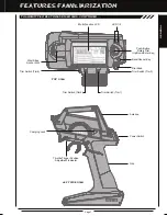
Back/Cancel Key:
Pressing the Back/Cancel Key returns the Programming Cursor to the previous menu. Press and HOLD the
Back/Cancel Key to return to the Top Screen.
Battery Compartment:
Houses the four 'AA' Alkaline cells that power the transmitter. Alternatively, the transmitter can be
powered using four 'AA' Ni-Cd or Ni-MH rechargeable batteries or a 2S Li-Po or 2S Li-Fe/A123 battery pack.
Bind Button:
Used in the process of Binding the transmitter and receiver.
Bind LED:
Displays the current status of the receiver.
Charging Jack:
Used for onboard charging of optional Ni-Cd or Ni-MH batteries. Do not attempt to charge Alkaline batteries.
If using an after-market Peak-Detection charger or other type of fast charger, the batteries should be removed from the
transmitter to avoid damage to the transmitter circuitry and/or your batteries.
Do not attempt to charge a Li-Po or Li-Fe/A123 battery pack through the Charging Jack.
Coaxial Cable:
The portion of the receiver antenna that extends the Antenna Reception Wire. The Coaxial Cable can be bent into
gentle curves, however, do not bend it acutely, or repeatedly bend it, or the antenna core can be damaged. The Coaxial Cable
should be installed into a nylon tube (antenna tube) and positioned vertically in your model for the best reception.
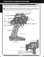
Dial Knob:
The Dial Knob can rotate 360º and is programmable to perform a different function depending on what function is
assigned to it. For example, it can be used to increase and decrease programming values, control a Trim function or control an
Auxiliary Channel.
Grip:
The Grip is molded from rubber in an ergonomic shape for increased comfort, control and feel. An optional Grip is included
LED 1/2:
Displays the current signal output status of the transmitter (LED 1 - Blue) and the Telemetry connection (LED 2 - Red).
In addition, one or both LEDs are used to indicate various transmitter conditions. For example, when a Throttle Offset percentage
Multi-Function LCD:
The heart of the programming and display features of the transmitter. All programming and transmitter
display functions are shown on the Multi-Function LCD.
For information about connecting the Telemetry Sensors, see the
Telemetry Connections and Mounting
section on page 13.
Bind Button
Coaxial Cable
Antenna
Reception
Wire
Bind LED
= Signal = Positive
= Negative
Telemetry Inputs
Steering (CH 1)
Throttle (CH 2)
Auxiliary 1 (CH 3)
Auxiliary 2 (CH 4)
FEATURES FAMILIARIZATION
RECEIVER FEATURES DIAGRAM
TRANSMITTER AND RECEIVER FEATURES DESCRIPTIONS
that is molded in a different shape that some users may find feels more comfortable.
value is programmed, the blue LED will flash.
Содержание MT-4
Страница 1: ...OPERATING MANUAL ...


