S&P EC-3N Скачать руководство пользователя страница 15

15

ENGLISH

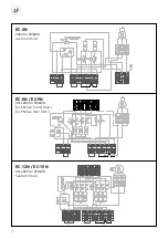
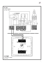
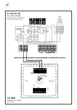
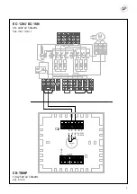
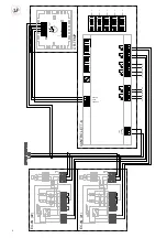
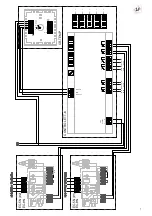
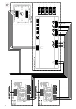
For connection, follow the installation procedure outlined 
for the commutation switch CR-25. 
For the electrical connections, see the thermostat dia-
grams (TR-1or TR-2).
The TR-1 thermostat can be used with models EC-3N, EC-
5N and EC-9N.
The TR-2 thermostat can be used with models EC12N and 
EC-15N. This thermostat allows an improvement in tem-
perature differential and energy savings. 

OPERATION 

The CR-25 commutator operates as described below.
The positions on the commutator are as follows:

0

Stop

Ventilation

Half power heating 

Full power heating

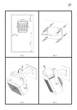
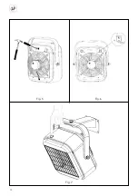
When the commutation switch at the rear of the apparatus 
(fi g.6) is in the position 

 the optional thermostat (TR-1 

or TR2) acts only on the heater elements, disconnecting 
them when the selected temperature is reached. The fan 
functions permanently. 
When the commutator is in position   the thermostat acts 
on the heater elements and the fan, both being disconnec-
ted when the selected temperature is reached.
The thermostat fi xes and maintains the desired tempera-
ture.
To operate, turn the thermostat control to the maximum 
position.
Select the power.
Once the surrounding area has reached the desired tem-
perature, slowly turn back the thermostat control an-
ti-clockwise until a slight “click” is heard. The Aeroheater 
will now connect and disconnect automatically, maintai-
ning the pre-selected temperature constant, according to 
the mode selected To disconnect: Situate the commutation 
switch in the “0” position. 

NOTE: the surfaces of the apparatus are hot during ope-
ration. 

OVERHEATING: SAFETY DEVICES 

The Aeroheaters incorporate thermal protection which 
prevents the apparatus from overheating by automatically 
disconnecting the apparatus. This device needs to be ma-
nually reset. If the device activates, wait for 15 minutes to 
allow the apparatus to cool, check that the grilles are not 
dirty and, if necessary, disconnect the apparatus from the 
mains supply and clean them.
To operate the apparatus again, push the RESET button lo-
cated at the top of the apparatus (fi g.7).
If the problem persists, contact S&P Offi cial Service Ne-
twork. 

MAINTENANCE 

• Disconnect the apparatus from the mains electricity 

supply, using the mains switch, before carrying out any 
maintenance operations. 

•  Each season, clean the accumulated dust from the inte-

rior of the apparatus using a compressed air jet to blow 
through the inlet and outlet grilles. This operation should 
be carried out by a qualifi ed technician.

•  Regularly clean the air inlet and outlet grilles.
•  Do not submerge the apparatus or place it below a tap. 
•  Do not disassemble or manipulate the apparatus, as this 

will invalidate the guarantee. 

A sensitive internal differential switch protects the applian-
ce which sometimes disconnects the apparatus from the 
supply. This is normally due to the presence of humidity 
in the heater elements. These elements may accumula-
te humidity in their interior when not used for long period 
of time. This is not considered as a defect. To correct the 
situation, connect the apparatus to the mains without the 
differential switch. The drying out period could last hours 
or even days. A good means to avoiding this situation is to 
operate the apparatus periodically. 

Note: 

To ensure safe and trouble free operation is very im-

portant that the appliance is cleaned at least once a year. 

Standards:

 These apparatus comply with the regulations 

governing radio-electrical interference, and has the requi-
red screening devices. 

TECHNICAL ASSISTANCE 

The extensive network of S&P Offi cial Service Agents gua-
rantees technical assistance in any place in Europe.
In the case that the product does not operate correctly, 
please contact any of the previously mentioned services to 
resolve the problem.
Any manipulation of the apparatus made by personnel 
other than S&P Offi cial Services will invalidate the guaran-
tee.
S&P reserve the right to modify the product without prior 
notice. 

Содержание EC-3N

Страница 1: ...EC 3N EC 5N EC 9N EC 12N EC 15N...

Страница 2: ...2 EC 3N 230V AC 50 60Hz 3x4 mm min EC 5N EC 9N 3N 400V AC 50 60Hz EC 5N 5x2 5 mm min EC 9N 5x4 mm min EC 12N EC 15N 3N 400V AC 50 60Hz 5x6 mm min m min N 5x4mm min...

Страница 3: ...3 5 6 7 COM 100 250V 50 60Hz 3 4 NO NC 16 17 GND RELAY 2 14 EC 3N 230V AC 50 60Hz 3x4 mm min CR TEMP 100 250V AC 50 60Hz 2x1 5 mm...

Страница 4: ...4 5 6 7 COM 100 250V 50 60Hz 3 4 NO NC 16 17 GND RELAY 2 14 EC 9N 5x4mm min EC 5N EC 9N 3N 400V AC 50 60Hz EC 5N 5x2 5 mm min EC 9N 5x4 mm min CR TEMP 100 250V AC 50 60Hz 2x1 5 mm...

Страница 5: ...5 EC 12N EC 15N 3N 400V AC 50 60Hz 5x6 mm min CR TEMP 100 250V AC 50 60Hz 2x1 5 mm 5 6 7 COM 100 250V 50 60Hz 3 4 NO NC 16 17 GND RELAY 2 14...

Страница 6: ...TEP OFF 1 2 3 4 2 3 4 5 6 1 10 11 12 13 14 15 RE5 RE4 16 17 18 19 20 21 22 23 24 25 RE3 RE2 RE1 9 38 STEP ON EC 3N 1 EC 3N 6 EC 3N 5 EC 3N 4 EC 3N 3 EC 3N 2 5 6 BLOCK 2 230V 50 60Hz ON 1 2 3 5 6 BLOCK...

Страница 7: ...2 3 4 5 6 1 2 3 4 1 10 11 12 13 14 15 RE5 RE4 16 17 18 19 20 RE3 RE2 22 23 24 25 RE1 21 BLOCK 1 9 38 STEP ON ON ON EC 5N 2 EC 5N 6 EC 9N EC 5N 5 EC 9N EC 5N 4 EC 9N EC 5N 3 EC 9N BLOCK 2 230V 50 60Hz...

Страница 8: ...22 23 24 25 21 RE2 RE1 16 17 18 RE3 ON CONTROL ETT 6 38 STEP ON 9 EC 12N 2 EC 15N EC 12N 1 EC 15N EC 12N 3 EC 15N EC 12N 3 EC 15N EC 12 15N 1 step 1 EC 12 15N 1 step 2 EC 12 15N 2 step 2 EC 12 15N 2...

Страница 9: ...9 Fig 1 Fig 3 Fig 2 Fig 4...

Страница 10: ...10 Fig 5 Fig 7 Fig 6...

Страница 11: ...11...

Страница 12: ...e deben ser incorporados a la instalaci n ja para su desconexi n omnipolar de la red de alimen taci n deben presentar una separaci n de contactos de al menos 3 mm en todos los polos IMPORTANTE Se tien...

Страница 13: ...r el aparato durante 15 minutos com probar que no haya acumulaci n de suciedad en las reji llas y si fuera preciso limpiarlas despu s de desconectar el aparato de la red Vuelva a poner en marcha el Ae...

Страница 14: ...hould include a double pole switch with a contact clearance of at least 3 mm IMPORTANT The apparatus should have suf cient space around it for the circulation of air g 1 The minimum distance between t...

Страница 15: ...nd if necessary disconnect the apparatus from the mains supply and clean them To operate the apparatus again push the RESET button lo cated at the top of the apparatus g 7 If the problem persists cont...

Страница 16: ...plaque caract risti que L installation doit pr voir une prise de terre Il est d conseill l utilisation de rallonge ou d adaptateur multiprises En cas de raccordement direct au r seau la ligne lectriqu...

Страница 17: ...URIT CONTRE LES SURCHAUFFES Les a rothermes sont quip s d une protection thermique r armement manuel arr tant automatiquement l appa reil en cas de surchauffe Au cas o cela se produirait laisser le re...

Страница 18: ...stromnetz an das das ger t anges chlossen wird muss geerdet sein Von der verwendung von adaptern und mehrfachs teckdosen wird abgeraten Bei der installation ist ein trennschalter mit einer trennstrec...

Страница 19: ...g abk hlen lassen Sicherstellen da die Gitter nicht verschmutzt sind und diese gegebenenfalls reinigen In diesem Fall ist das Ger t vom Netz zu trennen Den Heizl fter wieder in Betrieb setzen indem de...

Страница 20: ...om mutatore a quattro posizioni ed il termostato Le posizioni del commutatore in un senso o nell altro sono le seguenti 0 Arresto Ventilazione Met potenza di riscaldamento Piena potenza di riscaldamen...

Страница 21: ...o per un lungo periodo Questo non un diffetto Per rimediare a questo inconveniente collegare l apparecchio ad una pre sa di corrente senza interruttore differenziale Il tempo di asciugatura pu durare...

Страница 22: ...es nem bases m ltiplas Os dispositivos de corte que devem ser in corporados na instala o xa para o seu corte omnipolar da rede de alimenta o deve apresentar uma separa o de contac tos de pelo menos 3...

Страница 23: ...N o mergulhe o aparelho nem o coloque por baixo de tor neiras N o desmonte nem manipule o aparelho tal facto anula ria automaticamente a garantia Se a instala o estiver protegida por um interruptor di...

Страница 24: ...uiting aangesloten te worden op het span ningsnet en dient een dubbele poolschake laar te hebben met een contactruimte van tenminste 3 mm BELANGRIJK Rondom het apparaat dient voldoende ruimte aanwezig...

Страница 25: ...uitgeschakeld wordt wacht dan 15 minuten totdat het apparaat afgekoeld is Controleer vervolgens of de roosters niet vuil zijn en indien nodig schakel de span ning uit en reinig de roosters Om het over...

Страница 26: ...deras av en dubbelpolig omko pplare med kontaktavst nd av minst 3 mm VIKTIGT Apparaten m ste ha tillr ckligt avst nd runt om f r cirku lation av luften g 1 Kortaste avst ndet mellan Luftv rmaren och g...

Страница 27: ...e r smutsiga och om s r fallet koppla ur apparaten fr n str mf rs rjningen och reng r dem F r att starta appar ten igen tryck p RESET knappen ovanp apparaten Om problemet kvarst r kontakta S P Service...

Страница 28: ...beltpolskontakt der be nder sig mindst 3 mm fra andre elementer VIGTIGT Apparatet skal have plads nok til fri luftcirkulation g 1 Den minimale afstand mellem Aeroheateren og gulvet b r v re 1 8 m INST...

Страница 29: ...lysne ttet og rense ristene For at t nde for apparatet igen skal du trykke p knappen RESET der er placeret verst p apparatet Hvis problemet vender tilbage skal du kontakte S P s of cielle servicenetv...

Страница 30: ...n tak aby nebyl v dosahu osoby kter se sprchuje nebo koupe VSECHNY OHR VACE JSOU V EU CERTIFIKOV NY PRO MONT Z DO VLHK HO PROSTRED PRED MONT Z ZKONTROLUJTE ZDA DAJE NA ST TKU SOUHLAS S NAPET M A FREK...

Страница 31: ...ne Pri dosazen nastaven teploty se ohrev i ventil tor vypnou Pri poklesu teploty termostat ohrev nebo ohrev a ventil tor opet zapne a t m udrzuje teplotu v m stnosti na nastaven hodnote Pro nastaven z...

Страница 32: ...pro zajisten bezprobl mov ho provozu je treba pr stroj cistit alespon jednou za rok Normy Ohr vace splnuj pozadavky na rusen radiotechnickych pr stroju a jsou odpov daj c m zpusobem odruseny TECHNICK...

Страница 33: ...Wszystkie prace instalacyjne powinny zostac wykonane przez wykwalifikowany i upowazniony do tego personel zgodnie z regulacjami prawnymi obowiazujacymi w Polsce 2 Przew d zasilajacy powinien zostac t...

Страница 34: ...powinno byc wykonane izolowanym przewodem kt ry powinien zostac wprowadzony do urzadzenia przez listwe zaciskowa PODLACZENIE PRZELACZNIKA CR 25 Termowentylator moze zostac podlaczony do sieci poprzez...

Страница 35: ...asilania i skontaktowac sie z autoryzowanym serwisem dostawcy KONSERWACJA UWAGA PRZED PRZYSTAPIENIEM DO PRAC KONSERWACYJNYCH NALEZY UPEWNIC SIE ZE URZADZENIE JEST ODLACZONE OD SIECI ZASILAJACEJ Aby za...

Страница 36: ...36 EC N EU 2015 1188 2009 125 EC 5401652800 CR TEMP 50 3 1 fig 1 1 8 1 fig 1 1 2 fig 2 2 3 fig 3 S P 4 fig 4...

Страница 37: ...37 CR 25 CR 25 5 fig 5 CR 25 TR 1 TR 2 CR 25 TR 1 EC 3N EC5N EC 9N TR 2 EC 12N EC 15N CR 25 0 6 fig 6 TR 1 TR 2 6 fig 6 0 15 7 fig 7 S P...

Страница 38: ...38 Soler Palau Soler Palau...

Страница 39: ......

Страница 40: ...S P SISTEMAS DE VENTILACI N S L U C Llevant 4 Pol gono Industrial Llevant 08150 Parets del Vall s Barcelona Espa a Tel 34 93 571 93 00 Fax 34 93 571 93 01 www solerpalau com Ref 9023040600 03...

Отзывы: