S&C Instruction Sheet 765-510 27
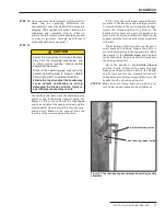
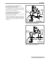
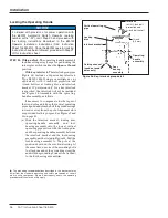
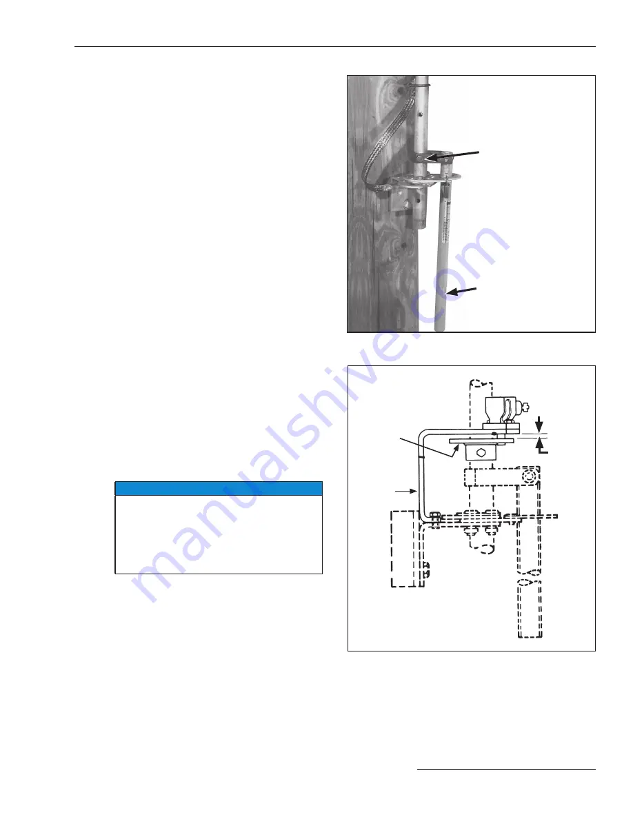
Figure 30. Key-interlock group detail.
Locking
disc
Interlock
bracket
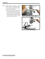
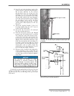
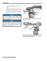
Figure 29. The foot-bearing assembly and operating-handle
assembly.
Handle
Piercing set screws
(b) Install the operating-handle assembly on the
lowest section of vertical operating pipe at
the location indicated in the erection
drawing. Make sure the cutting tip of the
piercing set screw in the operating-handle
assembly does not protrude when installing
the assembly on the vertical operating pipe.
After the operating handle is in place, tighten
the piercing set screw on the operating-
handle assembly, piercing the pipe. Continue
turning until a fi rm resistance is felt. See
Figure 29.
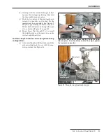
(c) Attach the interlock bracket to the foot-
bearing assembly, using the
½
–13
×
1 screws
and lockwashers furnished.
(d) Attach the key interlock to the interlock
bracket and extend the bolt.
(e) With the interrupter switch in the
Closed
position, use the interlock bolt to position
the locking disc so the bolt enters the closed-
position slot in the disc (and will enter the
open-position slot when the switch is in the
Open
position). Hold the locking disc
⅜
-inch
below the interlock bracket (see Figure 30)
and drill
7/16
-inch holes through the vertical
operating pipe section, using the holes in the
locking-disc collar as pilots. Attach the
locking disc to the pipe using the
⅜
–16
×
3
bolt, nut, and lockwasher furnished.
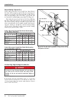
(f) Block one of the two slots in the locking disc
with the blocking screw provided. The slot
to be blocked will be determined by whether
a locked-open or locked-closed arrangement
is required.
NOTICE
Key interlocks are intended for proper
sequencing of switching operations; they
are not intended to provide security. The
operating-handle assembly includes swing-
away hasps for padlocking the interrupter
switch in either the
Open or Closed position.
Complete the operating-handle installation as directed
in Steps 10 through l4 on pages 16 and 17. Proceed to
page 28 for instructions on checking switch operation and
adjustment.
⅜
-inch
(9.5 mm)
Installation


