26 S&C Instruction Sheet 765-510
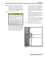
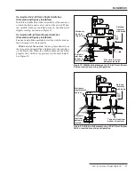
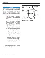
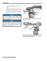
Figure 28. Key-interlock group detail.
Interlock
(with
⅜
-inch bolt
projection and
¾-inch bolt travel)
Vertical operating
pipe
Locking
disc
Interlock bracket
Gaining channel
(used on round
poles only)
Foot-
bearing
assembly
Operating-
handle
assembly
⅜
-inch
(9.5 mm)
Locking the Operating Handle
NOTICE
If ordered with provisions for power operation with
the 6801M Automatic Switch Operator (catalog
number suffix “-M”), omit Step 20 and proceed with
the locking instructions described in the 6801M
Operator installation instructions (S&C Instruction
Sheet 1045M-510). Once the 6801M operator locking
instructions have been followed, proceed with Step 21
of this instruction sheet.
STEP 20.
With padlock:
The operating-handle assembly
includes swing-away hasps for padlocking the
interrupter switch in either the
Open
or
Closed
position.
With key interlock:
The interlock group (see
Figure 28) includes a Superior key interlock,
Type B6003-1 Mk II single or multiple key (or
equivalent), with
⅜
-inch bolt projection and
¾-inch bolt travel, locking disc, and interlock
bracket. If “provision only” for a key interlock
is specified, the interlock will not be included.
See Figure 28. Assemble with the operating-
handle assembly as follows:
If necessary to compensate for the taper of
the wood pole and to keep the vertical operating
pipe aligned and plumb, shift the guide bearings
toward or away from the pole. Alignment slots
are provided for this purpose. See Figures 9 and
10 on page 15.
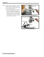
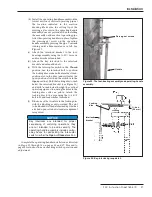
(a) Slide the interlock bracket, locking disc,
operating-handle assembly, and foot-
bearing assembly onto the lowest vertical
operating pipe section with the locking disc
and the operating-handle assembly between
the interlock bracket and the foot-bearing
assembly, as illustrated in Figure 28. Bolt the
foot-bearing assembly to the pole at the
position shown on the erection drawing. At
the same time, use one of the mounting bolts
to attach one end of the grounding strap (the
end with the grounding connector attached)
to the foot-bearing assembly
●
.
●
The grounding recommendations described in this document may
differ from the standard operating and safety procedures of certain
electric utility companies. Where a discrepancy exists, the operating
procedures of the electric utility apply.
Installation


