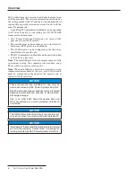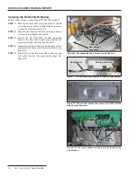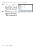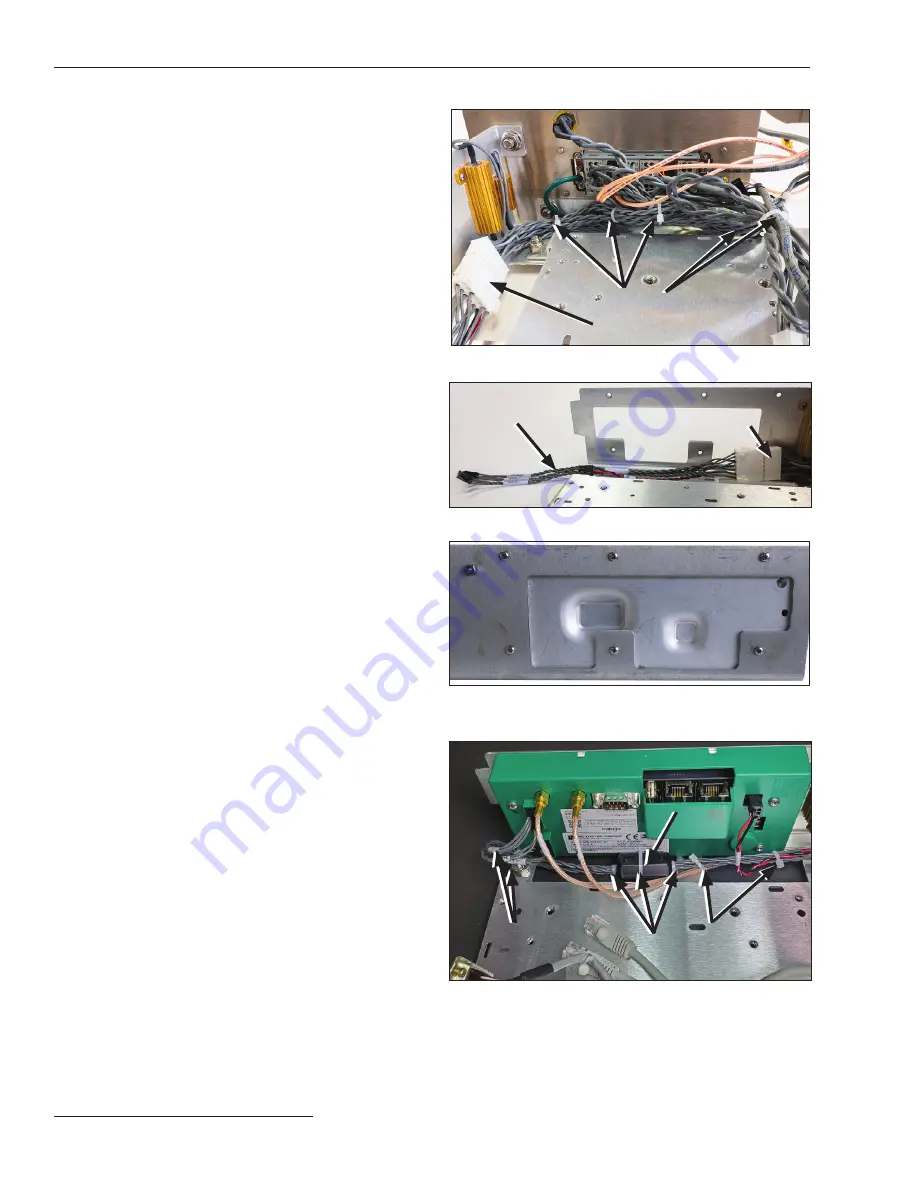
Figure 10. The rebundled cable harness and cable ties.
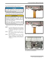
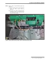
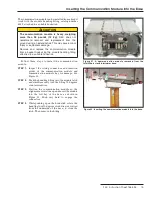
Figure 11. The new harness connected to the existing connector.
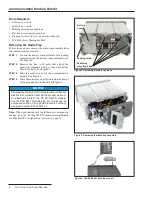
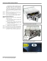
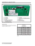
Figure 12. The six new screws that secure the R3 Wi-Fi/GPS
module mounting plate.
Installing the R3 Wi-Fi/GPS Module
Follow these steps to install the R3 Wi-Fi/GPS module.
STEP 1.
Fold the harness that was connected to the R0
circuit board as shown in Figure 10 and secure
it with the indicated cable ties.
STEP 2.
Plug the new harness into the existing harness
connector. See Figures 10 and 11.
STEP 3.
Install the R3 Wi-Fi/GPS module mounting
plate to the side of the radio tray with the six
screws provided. See Figures 12 and 13.
STEP 4.
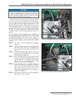
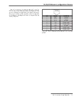
Install the ferrite choke around the gray cables
and install the three cable ties at the ferrite. See
Figure 13.
STEP 5.
Install two cable ties near the connector and
two cable ties near the gray cable plugs. See
Figure 13.
Existing connector
New harness
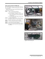
Figure 13. The ferrite choke and cable ties installed on the
new harness.
Cable ties
New harness
connector
Ferrite
choke
2 cable
ties
3 cable
ties
2 cable
ties
Communication Module Retrofit
10 S&C Instruction Sheet 766-526


