Setting the R3 Communication Module to Ethernet IP Configuration
NOTICE
Proper grounding with a wrist strap connected to
ground is required when touching any components
within the communication module or contacts on the
R3 Communication Module connector .
The R3 Communication Module is shipped from the
factory with a serial communication configuration.
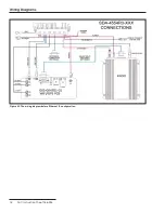
See the wiring diagram in Figure 26 on page 18. This
section instructs configuring the module to use the
Ethernet IP configuration, which allows remote access
to the WiFi/GPS user interface, enables remote firmware
updates, and allows use of advanced security features
available in the R3 Communication Module firmware
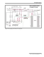
version 3.0.00512. See the wiring diagram in Figure 27 on
page 19.
To configure the R3 Communication Module for
Ethernet IP wiring, WAN traffic must be routed through
the Wi-Fi/GPS module. Follow these steps to convert the
R3 Communication Module from the serial communica-
tion configuration wiring to the IP configuration module
wiring:
STEP 1.
See page 9 for R3 Communication Module
removal.
STEP 2.
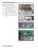
At the communication device, unplug the RJ45
cable that runs between the communication
device and the control module. See Figure 14 on
page 11.
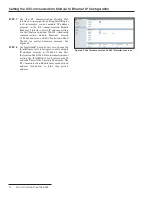
STEP 3.
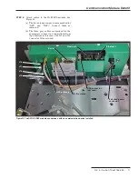
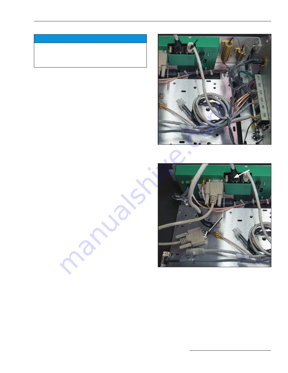
At the Wi-Fi/GPS module, plug the RJ45 cable
from the control into Ethernet 1 on the Wi-Fi/
GPS module. See Figure 18
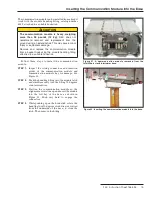
STEP 4.
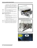
Locate the Ethernet patch cord provided with
the R3 Communication Module and plug one
end into Ethernet 2 on the Wi-Fi/GPS module
and the other into the Ethernet port on the
communication device. See Figure 19.
STEP 5.
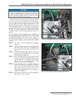
Install the DB-9 cable to the field communica-
tion device so Wi-Fi can communicate with that
device. See S&C Instruction Sheet 766-528
with module firmware version 3.0.00512, or
Instruction Sheet 766-524 for other firmware
versions. See Figure 19.
STEP 6.
Follow instructions in the the “Reinstalling the
Radio Tray” section on page 12.
Figure 18. The RJ45 cable from the control plugged into Ethernet 1.
Ethernet 1
Figure 19. The Ethernet patch cord plugged into Ethernet 2.
Ethernet 2
DB-9 cable to
comm device
S&C Instruction Sheet 766-526 13


