background image

35

- As the micom wash machine is configured of the complicate structure, there might be the service

call.

Below information is prepared for exact trouble diagnosis and suitable repair guide.

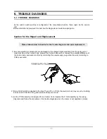
Caution for the Repair and Replacement

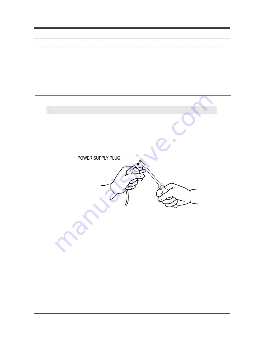
1) As some electronic components are damaged by the charged static electricity from the resin part of

wash machine or the human body, prepare the human body earth or remove the potential difference of
the human body and wash machine by contacting the power supply plug when the work contacting to
PCB is executed.

2) Since AC220~240V is applied to the triac T1 and T2 on P.C.B, the electric shock may occur by touching

and be careful that the strong and weak electricity are mixed.

3) As the P.C.B assembly is designed for no trouble, do not replace the P.C.B assembly by the wrong

diagnosis and follow the procedure of the trouble diagnosis when the micom is not operated normally.

Please follow below instruction for the trouble diagnosis and parts replacement.

6.

TROUBLE DIAGNOSIS

6-1. TROUBLE DIAGNOSIS

Содержание WF-F1256

Страница 1: ...es 3 Calm Wash 4 Child Lock 5 Prewash WF F1256 YLP F1056 YLP F856 YLP BASIC MODEL F1245AVGW YLP SERVICE Manual F1256 THE FEATURE OF PRODUCT Refer to the service manual in the itself http itself sec sa...

Страница 2: ...POINT 3 5 DESIGNATION OF MAIN COMPONENTS 4 ALIGNMENT AND ADJUSTMENTS 4 1 GENERAL ERROR FUNCTION 4 2 TEST MODE 5 ASSEMBLE AND DISASSEMBLE 5 1 TOOLS FOR DISASSEMBLY AND ASSEMBLY 5 2 ASSEMBLE AND DISASSE...

Страница 3: ...9 1 EMZ F1256 F1056 9 2 ROLD F856 10 PCB CIRCUIT DIAGRAM 10 1 PCB CIRCUIT DIAGRAM 11 REFERENCE INFORMATION 44041 PRGHO QDPH 44051 WHUPLQRORJ 44061 IDEULF FDUH FKDUW 44071 HOHFWULFDO ZDUQLQJV 44081 T D...

Страница 4: ...LL BUZZER1 LED9 DGND LED19 D12 DGND D18 D5 D6 D11 1N4148 R51 1K 5V PTC 270M 1N4148 270K R40 D30 D33 1N4148 LED15 10K R38 R32 270K 5V 100nF C19 D31 LED34 LED38 SW4 5V C10 100nF ZD1 R16 100K D29 1N4007...

Страница 5: ...44 R0019 D0003 R0036 C0002 C0115 F0125 D0081 D0061 D0112 D0075 D0046 C0058 7 EXPLODED VIEWS AND PARTS LIST...

Страница 6: ...45 R0158 I0043 U0355 U0095 U0010 U0015 U0307 U0033 U0016 U0018 D0048 R0030 U0029 U0038 U0355 U0355...

Страница 7: ...46 W0004 W0001 R0148 R0027 P0001 Y0040 W0002 I0022 F0027 B0070 I0003 A0006 J0013 A0025 R0159 R0159 W0032 R0158...

Страница 8: ...A ASSY LEVER DOOR Q1636GW XEU TS 2 PJT 1 SA D0048 DC61 00933A BRACKET HINGE Q1636GW XEU SBHG T 1 SA D0061 DC64 00920A DOOR GLASS R831 GLASS NTR CKD C 1 SA D0072 DC61 00891A GUIDE HINGE HAUZEN DOM POM...

Страница 9: ...L123 25 ZPC YEL SWRCH18A W 1 SA U0320 6011 001448 BOLT HEX M8 L170 25 ZPC YEL SWRCH18A W 1 SA U0320 DC60 40141A BOLT HEX SM10C DAMPER HEX M8 L66 ZPC2 2 SA U0320 DC60 40144A BOLT HEX M10 L41 ZPC2 YEL...

Страница 10: ...M DRIVE CONTROL TRIAC DRIVE CONTROL RELAY WATER LEVEL SENSOR WATER THERMISTOR HEAT SINK THERMISTOR OSCILLA TION CIRCUIT RESET CIRCUIT EEPROM CIRCUIT AC ZERO CROSSING DETECT CIRCUIT PRE WASH WASH RINSE...

Страница 11: ...on a firm and leveled floor Keep it away from direct sunlight or high humidity and install it in a place with good ventilation Keep the unit away from places in which it is freezing especially in win...

Страница 12: ...over the Wash Basin or Laundry Tub or plug the end of the drain hose into the Standpipe The end of the drain hose must be passed through the Hose Guide or secured as shown in the picture to prevent i...

Страница 13: ...leveling legs The 4 leveling legs should touch the floor all together Caution Tighten the lock nut after the leveling If not it could generate vibrations noises When the unit is not leveled Lift up t...

Страница 14: ...nplug it by holding the plug Beware of possibility of electric shock or fire when the power cord is damaged 12 Unplug the power plug from the outlet when the washing machine is not used Beware of poss...

Страница 15: ...ON WASHING 220 V 180 W 240 V 180 W WASHING and HEATING 220 V 1850 W 240 V 2150 W SPIN MODEL WF F1256 WF F1056 WF F856 220 240V 270 W 230 W 180 W PUMPING 34 W WATER CONSUMPTION 43 STANDARD COURSE SPIN...

Страница 16: ...6 2 2 OVERVIEW OF THE WASHING MACHINE...

Страница 17: ...6 0kg Model Name WF F1256 F1245AVGW Capacity Washing 4 5kg 4 5kg Drum Capacity 43 42 Washing Motor HXGP2I HXGN2I Heater 220V 1900W 1900W Supply Drain All temperatures Drain pump All temperature Drain...

Страница 18: ...DUCT 4 5kg Model Name WF F1256 WF F1056 WF F856 Function Water level Control O O O Add Laundry O O X Exterior Replacement Part Name Specifications Design Cover Door Neat White Neat White Neat White Ha...

Страница 19: ...9 3 PRODUCT SPECIFICATIONS 3 1 OVERVIEW OF THE CONTROL PANEL...

Страница 20: ...800 126 Coloureds 7 0 4 0 7 0 5 2 4 5 yes 60 1400 1200 1000 800 99 Synthetics 3 0 3 0 yes 60 800 800 800 800 72 Delicates 2 5 2 5 2 0 yes 40 800 800 600 600 55 Wool 2 0 2 0 1 5 1 5 1 5 1 5 yes 40 400...

Страница 21: ...WF J1056 R1056 F1056 WF R1256 R1056 R856 WF F1256 F1056 F856 WF R856 F856 WF J1456C J1256C J1056 WF J1256C R1256 F1256 PROGRAM Type of WASH Baby Cotton Averagely or lightly soiled baby cottons bed li...

Страница 22: ...l operating is halted and door error message will be displayed 2 digit panel displays dE 4 digit panel displays door and error melody will coming out Door open error can be cleared by closing the door...

Страница 23: ...For 10 minute late the variance of temperature Y is less than 2 HE2 message is displayed on the panel The value of the initial thermistor A1 is compared with that of the thermistor A2 in 11 minutes Y...

Страница 24: ...bubble detecting function stops and go on to the next process The bubble detecting function during washing dehydrating to rinse dehydrating after 2 times instant dehydrating and before main dehydratin...

Страница 25: ...attached to motor If the degree of unbalanced laundry is over 6 times to default value laundry balancing system carryies out feed back process 3 times 13 R P M control The rotating motor enables the m...

Страница 26: ...48 50 Handwash 2 58 2 58 50 Quick 12 8 12 8 50 Pre 10 10 10 10 50 B Cotton 8 12 8 12 45 B Coloureds 10 10 10 10 45 B Delicates 5 10 5 10 40 B Stain 10 10 10 10 45 unit sec unit rpm Model Course WF F12...

Страница 27: ...cates Washing 23 80 24 55 24 30 Rinse 23 65 24 55 24 30 Wools Handwash Washing 23 45 24 35 24 00 Rinse 23 15 24 35 24 00 Quick Washing 24 40 25 00 24 70 Rinse 23 80 25 00 24 70 B Cotton B Coloureds Wa...

Страница 28: ...rflow error 21 50 The water supplied reach 2 3 of door Bubble detectingatwashing rinse dehydrating 24 50 Bubble detecting water level Bubble detecting rinse water level 23 00 The water level which can...

Страница 29: ...ator coil CCW Figure1 Figure2 1 2 3 4 5 6 7 8 9 10 STATOR WASHING MOTOR TACHO HIGH SPEED STATOR PROTECTOR MIDDLE SPEED ROTOR 150 C H 7 STATOR 5 1 STATOR 5 1 ROTOR 8 9 TACHO 3 4 PROTECTOR 6 7 H mm Code...

Страница 30: ...hot water valve 1 way and a cold water valve 2way and water flow per Min in the valve is below 3 5 5 Shock absorber and buffer spring This wash machine is equipped with 2 Shock absorbers with same cap...

Страница 31: ...EMARK I 30 25 35 DC97 01463J WF F1256 WF F1056 WF F856 TYPE INNER BEARING A OUT BEARING B OIL SEAL C Assy Tub Back REMARK I 30 25 34 1 DC97 00214K WF F1256 WF F1056 WF F856 A C OIL SEAL INNER BEARING...

Страница 32: ...on according to type WF Washer Front Loading WD Washer Drier RPM Notation 800RPM 8 1000RPM 10 1200RPM 12 1400RPM 14 INTRO YR 2005 Service Code Actual Model Name in the Market BOM Model Code WF F 12 5...

Страница 33: ...ts water draining and displays OVER FLOW ERROR E3 on the LED 4 THERMISTOR Keeps sensoring and controlling the temperature inside the tube to keep it below your settings 5 ASSY THERMAL FUSE Anti Over H...

Страница 34: ...This is particularly effective for cleaning badly stained laundry 10 WEIGHT SENSOR The tube automatically rotates when no water is supplied to detect the laundry weight so that the proper wash time ca...

Страница 35: ...in mind Operate the appliance only from the type of power source indicated on the marking label If you are not sure of the type of power supplied to your home consult your appliance dealer or local p...

Страница 36: ...ended our engineer s inspection 8 DRUM WASHER MODEL NAME Q1 3 display part Display malfunction AS rerecomm ended In this case you are recommended our engineer s inspection 9 DRUM WASHER MODEL NAME Q1...

Страница 37: ...smell General consulting For the initial use of product It may appear during the operaiton with coupling each other but it carefully watched by the customers who are using more than for 3 years Is tha...

Страница 38: ...ER MODEL NAME Q1 3 1E front loading washing machine error E7 Water level sensor ERR AS rerecomm ended It may happen when there is a trouble in air hose or water level sensor In this case you are recom...

Страница 39: ...remains to clog Did the rinse agent drain immediately or part to put the rinse is clogged after putting the rinse agent The rinse agent does not drain only when putting it up to the reamer shaped cap...

Страница 40: ...whether there is foreign material inserted such a soil dust 62 DRUM WASHER MODEL NAME Q1 3 installation connection Consulting for installation of front loading washing machine General consulting The d...

Страница 41: ...Ltd MAY 2005 Printed in Korea Code No DC68 02485A This Service Manual is a property of Samsung Electronics Co Ltd Any unauthorized use of Manual can be punished under applicable International and or d...

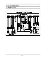
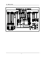
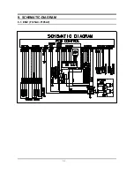
Страница 42: ...50 9 SCHEMATIC DIAGRAM 9 1 EMZ F1256 F1056...

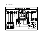
Страница 43: ...51 9 2 ROLD F856...

Страница 44: ...difference of the human body and wash machine by contacting the power supply plug when the work contacting to PCB is executed 2 Since AC220 240V is applied to the triac T1 and T2 on P C B the electric...

Страница 45: ...PCB assembly is out of order Replace it 5 The drum rotates by one direction during washing The drum rotates to one direction for SPIN The PCB assembly is out of order Replace it Inversion relay open...

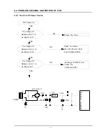
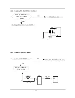
Страница 46: ...18 And Condenser CE3 Exchange IC3 7805 And Check The Condenser CE5 The Voltage Of Between and Is As Big As 12V The Voltage Of Between and Is As Big As 12V The Voltage Of Between and Is As Big As 5V NO...

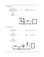
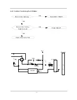
Страница 47: ...t Result Of Between Micom 25 And Gnd Is 5V Check The Power Source Check IC4 TR2 MMBT3904 67 R28 2 2K R35 4 7K R33 C13 C21 Check The Curve Output Of Check D11 12 16 17 18 Check The Micom Number 67 Chec...

Страница 48: ...rt Of Buzzer When The Micom 22 23 Check The Value Is 16Mhz Check Resonator Exchange Micom And Check R42 R41 Part Confirm DC12V Check The Part Of Power Source Exchange BUZZER1 Check R5 R46 NO YES NO YE...

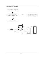
Страница 49: ...Is Not Operating But Pump Motor Is Operating Check The 5Voltage Of Micom Check The Micom 18th In The Above Method When The Cold Water Is Bad Micom Number 10 Is 5Voltage Micom Bad The Part Of Is 0 Volt...

Страница 50: ...Driving Part Of Motor Motor Is Not Spinning Check BD1 TRIAC5 Motor Is Not Turning Right And Left Check RELAY1 Check The Tacho Part YES YES NO NO BD1 RELAY1 D1 TRIAC5 CM5 R20 R18 1W 300 CM1 R6 COIL1 IC...

Страница 51: ...hecking The Tacho Part Have The Motor Turn In Hand Is The Rectangular Curve In The Micom 66 Check The Surroundings Circuit And TR1 IC7 Exchange The Motor NO YES R27 TR1 R30 R29 5V 5V IC7 C11 2 5 3 4 C...

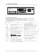
Страница 52: ...the Water Valve terminals 3 Drain Pump Check if it drains normally or check the pump terminals Check resistance of the Drain Pump terminals 4 Door S W Check if it works at the Cotton course or check...

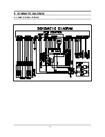
Страница 53: ...51 9 SCHEMATIC DIAGRAM 9 1 EMZ F125AC F105AV...

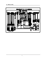
Страница 54: ...52 9 2 ROLD F85A...

Страница 55: ...51 9 SCHEMATIC DIAGRAM 9 1 EMZ F125AC F105AV...

Страница 56: ...52 9 2 ROLD F85A...

Страница 57: ...error and continuously progress water drain until the frequency reached 25 00kHz If Over Flow is also sensed even after the following check of water level frequency indicating that error it functions...

Страница 58: ...this error will occur Display 3E This error will be released by turning off Power S W 13 Motor TRIAC Short Error If Tacho signals are inputted more than 300 every 1sec in the operational interval less...

Страница 59: ...VALVE ON 0 3sec OFF 0 3sec HOT VALVE ON 0 3sec OPTION OFF 0 3sec Rinse VALVE ON 0 3sec OFF 0 3sec Pump MOTOR ON 0 3sec OFF 0 3sec MOTOR Left 0 5sec OFF 0 5 sec MOTOR Right 0 5sec OFF 0 3sec HEATER REL...

Страница 60: ...e shock absorber 1 Pulley hole 2 Double ended spanner 10 13 19mm Replaceable for the box driver Since the bolt runs idle when the box driver is used use the box driver 17mm 3 Vice pliers Tool to prote...

Страница 61: ...rt Name Descriptive Picture How To Do ASS Y COVER TOP Remove the two screws holding the Top Cover at the back of the unit Remove the top cover through pushing and pulling Then the Water Pressure Senso...

Страница 62: ...and the Ass y Drawer Remove the two screws on the front of the control panel Remove the control panel by disconnecting the connector that connects PCB to the wire harness Pry open the Cover Filter wit...

Страница 63: ...AME FRONT Remove the screw on Cover Front Insert a flat head screwdriver into the gap and pry down the Cover Front Left to separate it Remove the Wire Diaphragm from the Frame Front and unseat the Dia...

Страница 64: ...tom Remove the belt before the re assembly Ensure the belt is placed on the center of the motor pulley Belt Assembly Hang the belt on the motor pulley before placing it around the pulley Remove the wi...

Страница 65: ...screws for the water supply valve Disconnect the valve wires Separate the water hoses Water Level Sensor Remove the top cover Remove the fixing screws for the water level sensor Disconnect the water l...

Страница 66: ...the Door Hinge After putting them back together check if the screws holding the Door Hinge is fastened properly Drain Pump Insert the flat head screwdriver into the slot on the top of the Cover Filter...

Страница 67: ...e the Hose Filter Tub and the Drain Hose CHECK POINT 1 Remove the Drain Filter and check if there are foreign substances coin buttons etc blocking inside If so clear the inside 2 Check if the wire har...

Страница 68: ...nsert the flat head screwdriver and pry up the spring to remove the Spring Diaphragm The Diaphragm could get damaged when taking it out So unseat it in one direction slowly Remove the screws holding t...

Страница 69: ...the Heater and separate the Heater Take out the Heater from the Tub Caution Be sure to insert the Heater into the Bracket in the Tub If not it may cause a fire And make sure to have the Packing seati...

Отзывы: