


81
Ⅳ. ADJUSTMENT
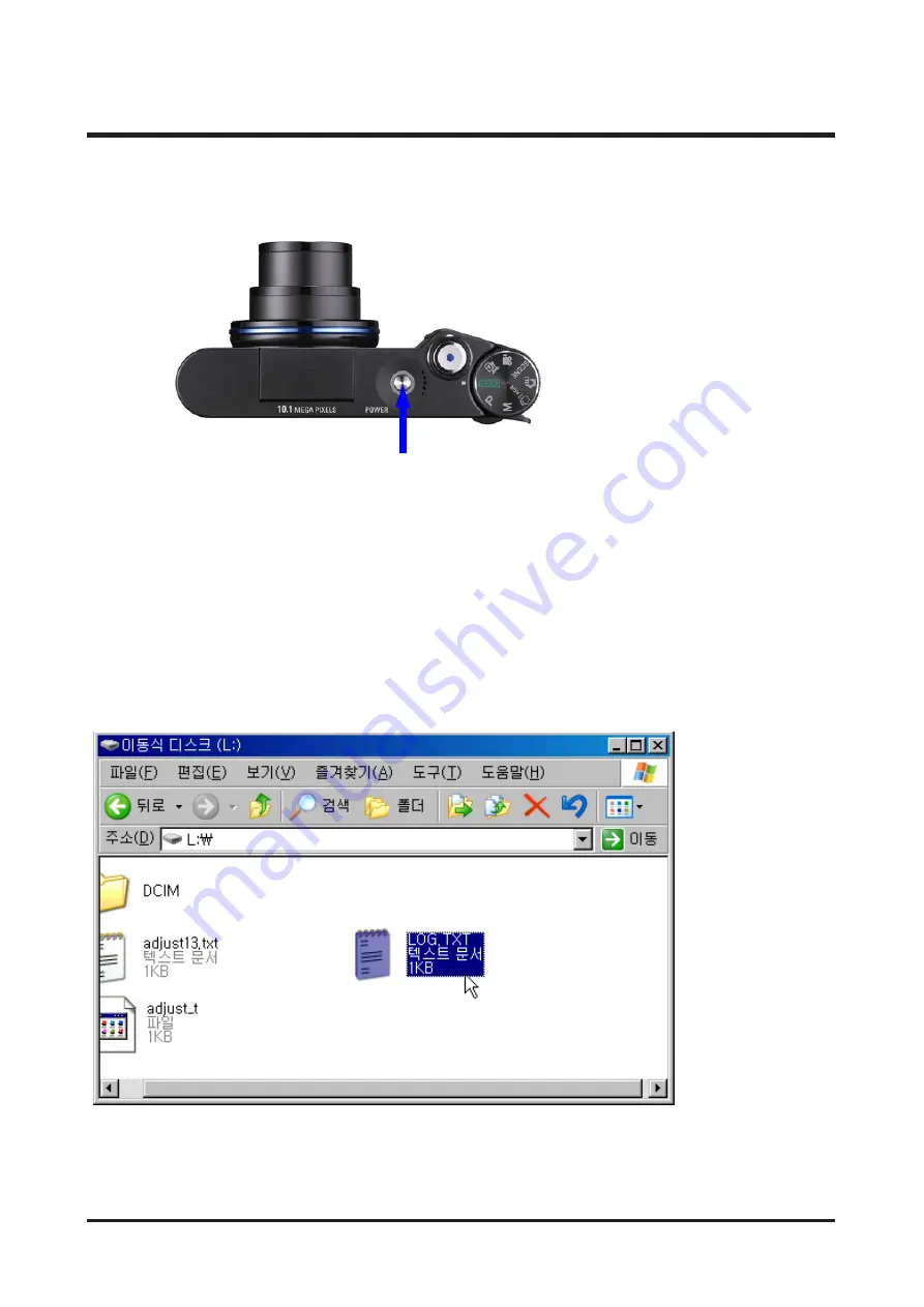
Turn on the camera and the adjustment mode will be selected automatically.
③
Reset the camera.
④
The procedures will be started.
⑤
While the procedure is done, the camera checks the battery level. If the level is good, OK message will display
and the procedure keeps going. If the level is bad, NG message will display and the procedure stops.
- OK message : Blinking AF lamp one time (OK message will be printed by the Serial port)
- NG message : Blinking AF lamp two times (NG message will be printed by the Serial port)
⑥
After completing the procedure, data that was saved on the cash memory temporarily are moved to the
FlashRom of the camera.(To write the data, the procedure must be complete. Data saved on the FlashRom is
not affected by the F/W update)
E. Log File Inspection
After completing the adjustment, LOG file will be made on the SD memory card.
Содержание VLUU NV10
Страница 1: ......
Страница 14: ...14 Ⅱ INSTALLATION FAQ 4 Install the Digimax Master in order ...
Страница 16: ...Ⅲ EXPLODED VIEW AND PART LIST 16 1 2 1 1 1 3 1 4 1 4 1 4 1 4 1 1 M MA AI IN N A AS SS SE EM MB BL LY Y ...
Страница 48: ...48 Ⅳ ADJUSTMENT 6 The Upgrade will start with displaying the following message ...
Страница 55: ...55 Ⅳ ADJUSTMENT Open the file with the Memo pad ...
Страница 75: ...75 Ⅳ ADJUSTMENT Open the file with the Memo pad ...
Страница 82: ...82 Ⅳ ADJUSTMENT Open the file with the Memo pad ...
Страница 105: ...Ⅴ PATTERN DIAGRAM 105 1 PARTS ARRANGEMENT FOR EACH PCB ASS Y 1 MAIN_TOP ...
Страница 106: ...106 Ⅴ PATTERN DIAGRAM 2 MAIN_BOTTOM ...
Страница 107: ...107 Ⅴ PATTERN DIAGRAM 3 STROBO_TOP ...
Страница 108: ...108 Ⅴ PATTERN DIAGRAM 4 STROBO_BOTTOM ...
Страница 109: ...Ⅵ CIRCUIT DIAGRAM 109 1 MAIN BLOCK DIAGRAM ...
Страница 110: ...110 Ⅵ CIRCUIT DIAGRAM 2 MAIN_AUDIO_VIDEO ...
Страница 111: ...111 Ⅵ CIRCUIT DIAGRAM 3 MAIN_DSP ...
Страница 112: ...112 Ⅵ CIRCUIT DIAGRAM 4 MAIN_PANASONIC 10M_NN12068A ...
Страница 113: ...113 Ⅵ CIRCUIT DIAGRAM 5 MAIN_MEMORY DDR FLASH ...
Страница 114: ...114 Ⅵ CIRCUIT DIAGRAM 6 MAIN_PIC_MICOM ...
Страница 115: ...115 Ⅵ CIRCUIT DIAGRAM 7 MAIN_MOTOR IC ...
Страница 116: ...116 Ⅵ CIRCUIT DIAGRAM 8 MAIN_POWER ...
Страница 117: ...117 Ⅵ CIRCUIT DIAGRAM 9 MAIN_CRADLE ...
Страница 118: ...118 Ⅵ CIRCUIT DIAGRAM 10 MAIN_LCD ...
Страница 119: ...119 Ⅵ CIRCUIT DIAGRAM 11 MAIN_TOP KEY ...
Страница 120: ...120 Ⅵ CIRCUIT DIAGRAM 12 TOUCH KEY ...
Страница 121: ...121 Ⅵ CIRCUIT DIAGRAM 13 STROBO ...
Страница 122: ...122 Ⅵ CIRCUIT DIAGRAM 14 24PIN CRADLE CONNECTOR ...
Страница 123: ...123 Ⅵ CIRCUIT DIAGRAM 15 MAIN_STR CONNECTOR ...
Страница 124: ...124 Ⅵ CIRCUIT DIAGRAM 16 SUB BLOCK DIAGRAM ...
Страница 125: ...125 Ⅵ CIRCUIT DIAGRAM 17 SUB_FPCB TO MAIN ...
Страница 126: ...126 Ⅵ CIRCUIT DIAGRAM 18 CASIO_LCD ...
Страница 127: ...127 Ⅵ CIRCUIT DIAGRAM 19 TELE_WIDE ...
Страница 128: ...128 Ⅵ CIRCUIT DIAGRAM 20 TOUCH_PAD ...
Страница 129: ...129 Ⅵ CIRCUIT DIAGRAM 21 TACT_FPCB ...
Страница 130: ...130 Ⅵ CIRCUIT DIAGRAM 22 TOP POWER MODE KEY ...
Страница 131: ...131 Ⅵ CIRCUIT DIAGRAM 23 BLOCK DIAGRAM ...
Страница 140: ...140 Ⅶ SERVICE INFORMATION 20 Disassemble the TROBE PCB 21 Remove 3 screws Disassembling the Barrel ASSY ...
Страница 141: ...141 Ⅶ SERVICE INFORMATION 22 Disassemble the Barrel ASSY 3 Disassemble the LCD PCB ...
Страница 144: ...144 Ⅶ SERVICE INFORMATION 4 Assemble two screws 5 Place the LCD PCB under the Barrel ...
Страница 145: ...145 Ⅶ SERVICE INFORMATION 6 Put the Barrel ASSY as shown 7 Assemble 3 screws 8 Put the STROBO PCB as shown ...
Страница 151: ...151 Ⅶ SERVICE INFORMATION 24 Assemble 4 screws 25 Assemble 2 screws 26 Assemble 4 screws ...
Страница 153: ...153 Ⅶ SERVICE INFORMATION 4 Remove 3 screws 5 Disassemble the LENS BASE and Barrel 6 Remove the Shutter PCB screw ...
Страница 157: ...157 Ⅶ SERVICE INFORMATION 16 Remove a screw 17 Disassemble the SHUTTER ASSY ...


