3
.
Installing the Product
80
English 8/2020. Rev 0.3
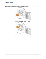
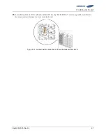
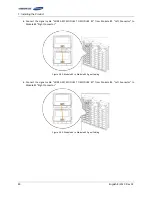
4.
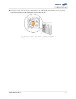
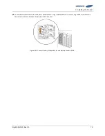
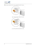
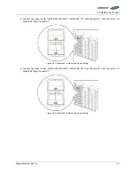
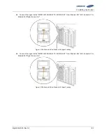
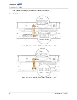
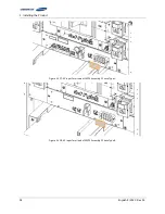
Connect the signal cable “WIRE ASSY MODULE TO MODULE #1" from Module #3 “Left Connector” to
Module #4 “Right Connector.”
Figure 3-93: Module #3 to Module #4 Signal Cabling
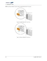
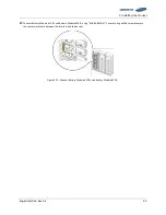
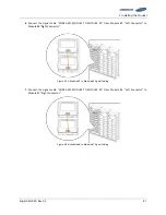
5.
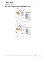
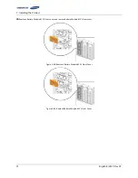
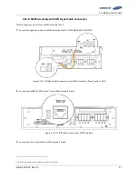
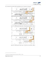
Connect the signal cable “WIRE ASSY MODULE TO MODULE #1" from Module #4 “Left Connector” to
Module #5 “Right Connector.”
Figure 3-94: Module #4 to Module #5 Signal Cabling
Содержание U6A4
Страница 1: ...English 8 2020 Rev 0 3 LIB System for UPS U6A4 Installation Manual 128S ...
Страница 4: ...English 8 2020 Rev 0 3 ...
Страница 10: ...Important Safety Instructions vi English 8 2020 Rev 0 3 ...
Страница 17: ...Table of Contents English 8 2020 Rev 0 3 vii ...
Страница 18: ......
Страница 60: ...3 Installing the Product 42 English 8 2020 Rev 0 3 Figure 3 33 Fuse Busbar Left Assembly Fuse Cover ...
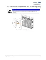
Страница 79: ...3 Installing the Product English 8 2020 Rev 0 3 61 Figure 3 63 Remove Battery Modules 9 s Front Cover ...
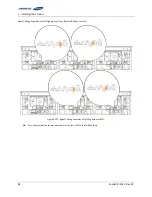
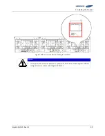
Страница 116: ...3 Installing the Product 98 English 8 2020 Rev 0 3 Figure 3 126 AC Input Terminals of SMPS Assembly 1 Phase Type B ...
Страница 125: ...Memo ...
Страница 126: ...Memo ...
Страница 127: ...Memo ...
Страница 128: ...www SamsungSDI com ...

