background image

E-

8

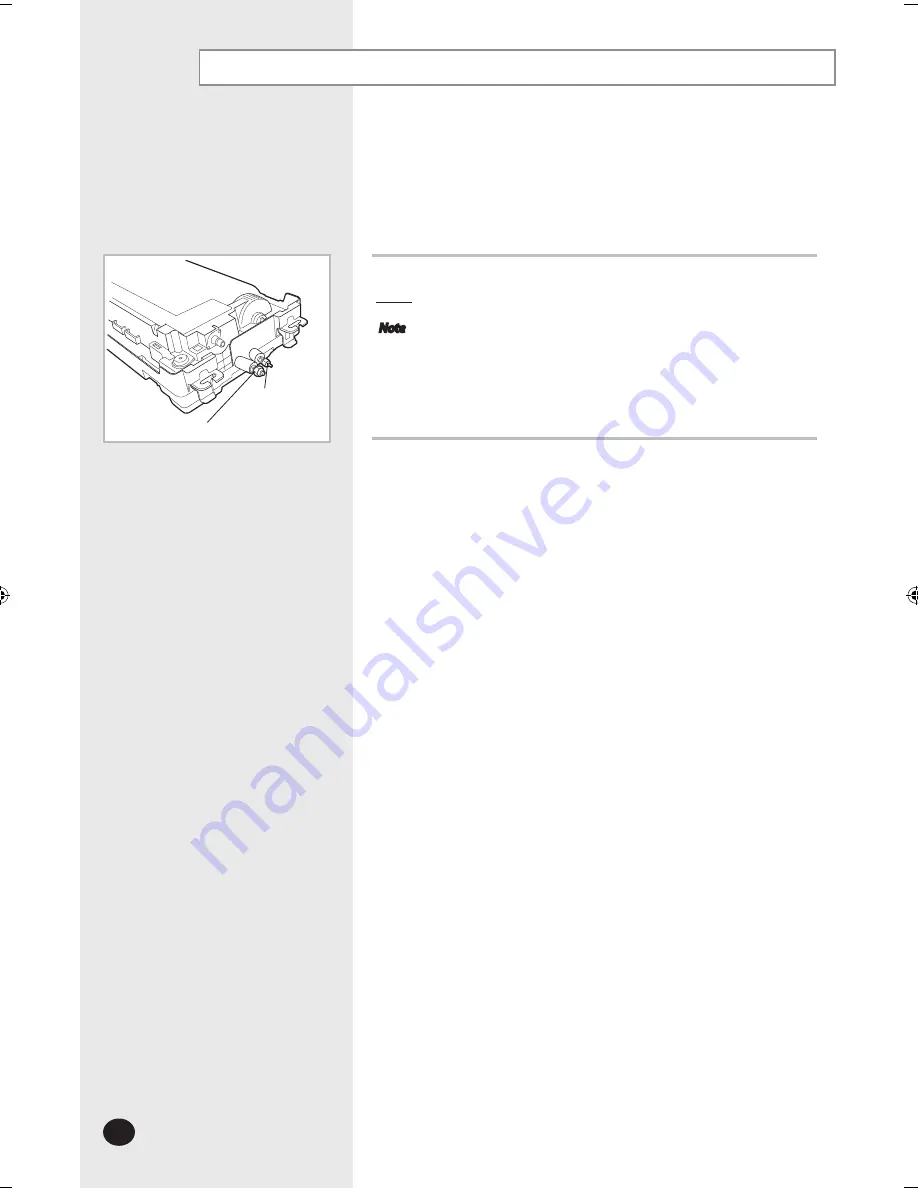
From factory the unit is supplied and set with a pre-charge of nitrogen gas 
(insert gas). Therefore, all insert gas must be purged before connecting the 
assembly piping.

Unscrew the pinch pipe at the end of each refrigerant pipe. 

Result

All inert gas escapes from the indoor unit.


Note


 To prevent dirt or foreign objects from getting into the pipes  
during installation, do NOT remove the pinch pipe completely  
until you are ready to connect the piping.

Purging the unit

Gas refrigerant port

Liquid refrigerant 

port

SH@@@EAV@_IM_E_28847-1.indd   8

2007-12-07   ソタネト 6:10:40

Содержание SH-EAV Series

Страница 1: ...ENGLISH System Air Conditioner Cooling and Heating INSTALLATION MANUAL CassetteType Series SH EAV ESPAÑOL FRANÇAIS ITALIANO PORTUGUÊS DEUTSCH EΛΛHNIKA RUSSIAN DB98 28847A 2 S E F I D P G R ...

Страница 2: ...nit If performed by unauthorized personnel these operations may cause electric shocks or fires Do not place containers with liquids or other objects on the unit All the materials used for the manufacture and packaging of the air conditioner are recyclable The packing material and exhaust batteries of the remote control optional must be disposed of in accordance with current laws The air conditione...

Страница 3: ... Indoor unit installation 7 Purging the unit 8 Connecting the refrigerant pipe 9 Cutting Flaring the pipes 10 Performing leak test insulation 11 Drainpipe and drain hose installation 12 Connecting the connection cord 14 Assigning address to indoor unit 15 Troubleshooting 16 Additional Accessories 20 ...

Страница 4: ...sed for laundry In areas where curtains and furniture could affect the supply and discharge of air Without leaving the required minimum space around the unit as shown in the drawing In scarcely ventilated areas On surfaces that are unable to support the weight of the unit without deforming breaking or causing vibrations during the use of the air conditioner In a position that does not enable the c...

Страница 5: ...t touchable by the users Space requirements for indoor unit The units must be installed according to distances declared in order to permit accessibility from each side either to guarantee correct operation of maintenance or repairing products The unit s parts must be reachable and removable completely under safety condition for people or things CAUTION As a rule the unit cannot be installed at a h...

Страница 6: ...pe connection ø6 35 2 Gas pipe connection ø9 52 3 Drain pipe connection OD 29 ID 25 4 Power supply connection 5 Air discharge grille 6 Air suction grille Dimension and weight Net dimension Indoor unit mm 970X135X410 Panel size 1180X25X460 Outdoor unit 790X548X285 Net weight Indoor unit Panel kg 13 Outdoor unit 32 6 Drain hole ...

Страница 7: ...ing the indoor unit CAUTION You must install all the suspension rods 5 Hang the indoor unit to the suspension bolts between two nuts Note Piping must be laid and connected inside the ceiling when suspending the unit If the ceiling is already constructed lay the piping into position for connection to the unit before placing the unit inside the ceiling 6 Screw the nuts to suspend the unit Cut a pad ...

Страница 8: ...ssembly piping Unscrew the pinch pipe at the end of each refrigerant pipe Result All inert gas escapes from the indoor unit Note To prevent dirt or foreign objects from getting into the pipes during installation do NOT remove the pinch pipe completely until you are ready to connect the piping Purging the unit Gas refrigerant port Liquid refrigerant port ...

Страница 9: ...or wave on the bended area 5 It would be necessary to double the insulation thickness 10mm or more to prevent condensation even on the insulator when if the installed area is warm and humid 6 Do not use joints or extensions for the pipes that connect the indoor and outdoor unit The only permitted connections are those for which the units are designed Refrigerant oil Spanner Union Torque wrench Fla...

Страница 10: ...88 mm 5 8 19 05 mm 3 4 1 3mm 1 8mm 2 0mm 2 2mm 2 2mm 5 Check that the flaring is correct referring to the illustrations below for examples of incorrect flaring 6 Align the pipes and tighten the flare nuts first manually and then with a torque wrench applying the following torque Valve Flare nut Valve cap Pressure port cap Valve needle Pressure port Wrench mm N m Wrench mm N m Wrench mm N m Wrench ...

Страница 11: ...oblems place T13 0 or thicker Acrylonitrile Butadien Rubber separately around each refrigerant pipe Note Always make the seam of pipes face upwards 2 Wind insulating tape around the pipes and drain hose avoiding to compress the insulation too much 3 Finish wrapping insulating tape around the rest of the pipes leading to the outdoor unit 4 The pipes and electrical cables connecting the indoor unit ...

Страница 12: ...cover drain Band Not supplied Adhesives Band Drain hose Flexible hose Drain hose port CAUTION Do not give the hose and upward gradient after the connection port This will cause water to flow backwards when the unit is stopped resulting in water leaks Air ventilation Ceiling Check that the indoor unit is level with the ceiling by using the leveler Install air ventilation to drain condensate water s...

Страница 13: ...ou do not pour water inside the water supply intake water may spill from the indoor unit 3 Confirm that the water flows out through the drain hose Note You can check the drainage only when the air conditioner is in cool mode 4 Reassemble the cover drain pump Note If a concentrated drain hose is installed refer to the figure below Concentrated drain hose 100mm or more 1 100 or more slope Drain clam...

Страница 14: ...he cable to the outdoor unit through the ceiling the hole on the wall 4 Reassemble the electrical component box cover carefully tightening the screw Wiring diagram Indoor unit Outdoor unit Communication Power Indoor Outdoor units Power 10 Power cable Max Length Power supply 220 240V 50Hz 0 75mm2 3wires 1Km Communication 0 75mm2 2wires 1Km Size of the cables used to interconnect the indoor and outd...

Страница 15: ...the air conditioner properly 4 It is required to set the RMC address if you install the centralized control and or the centralized control 5 If you install optional accessories such as the wired remote control centralized control etc see an appropriate installation manual 6 If an optional accessory is not installed you do not have to set the RMC address However adjust K1 and K2 switches of the SW0...

Страница 16: ...mmunication for 2 minutes between indoor units Communication error for more than 2 minutes 2 Indoor unit receiving the communication error from outdoor unit 3 Outdoor unit tracking 3 minutes error 4 When sending the communication error from the outdoor unit the mismatching of the communication numbers and installed numbers after completion of tracking Communication error for more than 2 minutes X ...

Страница 17: ...D 5 2nd detection of High temperature DISCHARGE 6 6th detection of Compressor down due to freezing X Displays an error of all indoor units Outdoor unit displays separately Detection of the float switch X X Error of setting option switches for optional accessories X X Check the setting of the Solution parts DIP S W EEPROM error X IC51 Cold soldering No soldering Check the inferior accessories EEPRO...

Страница 18: ...indoor unit communication wire miss connection Connected to Power terminal Outdoor unit refrigerant Full leakage Gas leak Outdoor Fan 1 Error Outdoor Fan 2 Error Discharge over temperature Outdoor Unit Protection Control Error Inverter Compressor starting error Primary Current Over Trip error Inverter DC PEAK error O C Inverter Compressor Rotation error Inverter Current Sensor error Inverter DC LI...

Страница 19: ...ensor secession Indoor Eva In and Out sensor secession error Secondary Electronic heater sensor 1 error Secondary Electronic heater sensor 2 error Secondary Electronic heater sensor 3 error Indoor Float S W 2nd Detection Indoor fan error Mixed operation error EEPROM error EEPROM option setting error Error regarding special sales taxes Electronic heater discharge temperature protection error Electr...

Страница 20: ...tion manual 1 1 1 1 Additional Accessories For information on additional options and accessories see either product catalogue or accessories installation and user s manual Wireless Remote Controller Accessories Type B Batteries for remote controller M4x12 tapped screw Remote control holder User s manual Installation manual 2 2 1 1 1 Wireless remote controller 1 Wireless Remote Controller Accessori...

Страница 21: ...tter 1 Transmitter power cable Transmitter communication cable Installation manual 1 1 1 Transmitter accessories Note If you would like to install the centralized control you must install the transmitter in the outdoor unit 7 day scheduler 1 Cable tie Cable clamp M4x16 tapped screw User s manual Installation manual 2 2 4 1 1 7 day scheduler accessories ...

Страница 22: ......

Отзывы: