background image

7.Troubles

ERROR MES

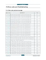
M1-1113

Paper jam in Tray 1

M1-1213

Paper jam in Tray 2

M1-1610

Paper jam in MP Tray

M2 1121

P

j

i T

1

M2-1121

Paper jam in Tray 1

M2-1124

Paper jam inside of machine

M2-1125

Paper jam inside of machine

M2-1131

Paper jam in Tray 2

M2-1134

Paper jam inside of machine

M2 1134

Paper jam inside of machine

M2-1135

Paper jam inside of machine

M2-1211

Paper jam inside of machine

M2-1213

Paper jam inside of machine

M2-1214

Paper jam inside of machine

M2-1321

Paper jam inside of machine.

M2-1324

Paper jam inside of machine

M2-1325

Paper jam inside of machine.

M2-1331

Paper jam inside of machine

M2-1333

Paper jam inside of machine

M2-1334

Paper jam inside of machine

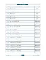
M2-2111

Paper jam inside of machine

M2-2113

Paper jam at the top of duplex path

M2-2114

Paper jam at the top of duplex path

M2-2213

Paper jam at the inside of duplex path

M2-2215

Paper jam at the inside of duplex path

M2-2216

Paper jam at the inside of duplex path

M2-2411

Paper jam at the inside of duplex path

M2-2413

Paper jam at the inside of duplex path

M2-2414

Paper jam at the return of duplex path  (display G

M3-1211

Paper jam in exit area

Service Manual

7-

shooting

SSAGE

PAGE

7-M-

1

7-M-

2

7-M-

3

7 M

4

7-M-

4

7-M-

4

7-M-

4

7-M-

4

7-M-

4

7 M

4

7-M-

4

7-M-

5

7-M-

5

7-M-

5

7-M-

6

7-M-

6

7-M-

6

7-M-

7

7-M-

7

7-M-

7

7-M-

8

7-M-

8

7-M-

8

7-M-

9

7-M-

9

7-M-

9

7-M-

10

7-M-

10

Graphical help)

7-M-

10

7-M-

11

SAMSUNG ELECTRONICS

-7

Содержание SCX-82x0 series

Страница 1: ... SCX 8230NA Ver 2 01 A3 Mono Copier Contents 1 Precautions 2 Product Description 3 Replacement Procedure 4 Service Mode 5 Updating Firmware 6 Preventive Maintenance 7 Troubleshooting 8 System Diagram 9 System Recovery 10 Reference Information ...

Страница 2: ...ocation 2 16 2 4 Paper handling section 2 20 2 4 1 Overview 2 20 2 4 2 Components 2 23 22 4 3 Functions 2 24 2 4 4 Paper tray 2 25 2 4 5 Pick up unit 2 26 2 4 6 Registration unit 2 27 2 4 7 MPF unit 2 28 2 5 Image creation 2 29 2 5 1 Printing process overview 2 29 2 5 2 Imaging unit 2 30 2 5 2 1 Imaging unit overview 2 30 2 5 2 2 Drum drive 2 31 2 5 2 3 Development 2 32 2 6 Fuser unit 2 34 ...

Страница 3: ...ve system 2 41 2 8 1 Drive Motors 2 41 2 8 2 Main drive unit 2 43 2 8 3 Pick up Drive 2 44 2 8 4 Fuser Exit Drive 2 45 2 8 5 Toner Duct drive 2 46 2 8 6 Drive of Toner Supply 2 46 2 8 7 WTB leveling drive 2 47 2 8 8 PR Release drive 2 47 2 9 Scanner system 2 48 2 9 1 Scanner System overview 2 48 2 9 2 Scanning System components 2 49 2 10 DADF 2 51 2 10 1 DADF System overview 2 51 2 10 2 Electric p...

Страница 4: ... 2 11 1 2 Fax Joint PBA 2 66 2 11 1 3 Primary Modem Card 2 67 2 11 1 4 Secondary Modem Card 2 68 2 11 1 5 FDI 2 69 2 11 2 OPE Controller 2 71 2 11 2 1 Sub Key PBA 2 73 2 11 2 2 USB Hub Controller PBA 2 74 2 11 3 DADF Controller 2 75 2 11 4 Interface Part 2 76 2 11 5 Connection Part 2 76 2 11 6 SMPS 1 2 77 2 11 7 SMPS 2 2 79 2 11 8 FDB 2 81 2 11 9 HVPS 2 82 2 11 10 Eraser PBA 2 83 2 11 11 Side Join...

Страница 5: ...2 88 3 Replacement produce 3 1 3 1 General precautions on disassembly 3 1 3 2 Cover 3 2 3 2 1 Front cover 3 2 3 2 2 Left cover 3 3 3 2 3 Rear cover 3 4 3 2 4 Right cover 3 5 3 3 OPE Unit 3 6 3 3 1 OPE assembly 3 6 3 3 2 OPE PBA and LCD panel 3 8 3 3 3 Key buttons 3 11 3 4 Scan unit 3 12 3 4 1 Scanner Assembly 3 13 3 4 2 Scan Glass 3 16 3 4 3 Lamp Assembly 3 17 3 4 4 Scanner Board 3 19 3 4 5 Scanne...

Страница 6: ...nsfer sensor 3 29 3 6 3 MP unit 3 31 3 6 3 1 MP Solenoid 3 33 3 7 Electrical components 3 36 3 7 1 Main board 3 36 3 7 2 Storage HDD 3 38 3 7 3 Toner PBA Toner Motor 3 39 3 7 4 Lift Motor 3 40 3 7 5 FDB 3 41 3 7 6 HVPS 3 42 3 7 7 SMPS 3 43 3 7 8 SMPS Fan 3 44 3 7 9 Ozone filter Fan 3 45 3 7 10 Side Joint PBA 3 46 3 7 11 Eraser Lamp 3 47 3 7 12 Waste Sensor PBA 3 48 3 7 16 Temperature sensor 3 49 ...

Страница 7: ...ease Drive unit 3 55 3 12 Pick up Drive unit 3 56 3 13 WTB Leveling Drive unit 3 57 3 14 LSU 3 60 3 15 Frame Duct 3 63 3 16 DADF 3 64 3 16 1 DADF Cover 3 65 3 16 2 DADF Open Cover 3 67 3 16 3 DADF Stacker 3 67 3 16 4 DADF main board 3 68 3 16 5 DADF motor solenoid clutch 3 69 3 16 6 DADF Detect Cover Regi sensor 3 71 3 16 7 DADF Exit Idle sensor 3 72 3 16 8 DADF Exit sensor 3 72 3 16 9 DADF Length...

Страница 8: ...ervice Functions 4 5 4 3 Information 4 6 4 3 1 General 4 6 4 3 2 Supply Status 4 6 4 3 2 1 Customer Replacement Unit CRU 4 6 4 3 2 2 Field Replacement Unit FRU 4 6 4 3 3 Software Version 4 8 4 3 4 Service Hours 4 8 4 3 5 Fault Log 4 8 4 3 6 Print Report 4 9 4 4 Maintenance Counts 4 10 4 4 1 Fault Count 4 10 4 4 2 Jam Count 4 11 4 4 3 Part Replacement Count 4 13 4 5 Diagnostics 4 14 4 5 1 Engine Di...

Страница 9: ...ines 4 25 4 5 4 Adjustment 4 27 4 5 4 1 Print Adjustment 4 27 4 5 4 2 Copy Adjustment 4 29 4 5 4 3 Scan Area Adjustment 4 30 4 5 4 4 DADF Adjustment 4 32 4 5 4 5 Finisher Adjustment 4 34 4 5 4 6 Buckle Adjustment 4 37 4 5 5 ACS 4 38 4 5 6 Color Management 4 39 4 5 6 1 Scan CTD 4 39 4 6 Service Functions 4 41 4 6 1 Main Memory Clear 4 41 4 6 2 Hard Disk Maintenance 4 41 4 6 3 Debug Log 4 41 4 6 4 P...

Страница 10: ...nce 6 1 6 1 PM Supplies 6 1 6 1 1 PM Parts 6 1 6 1 2 PM KIT 6 4 6 2 PM Procedures 6 5 6 2 1 Toner cartridge 6 5 6 2 2 Imaging unit 6 7 6 2 3 Transfer roller Unit 6 11 6 2 4 Fuser unit 6 12 6 2 5 Pick up Retard Forward roller 6 13 6 2 6 Ozone filter 6 13 6 2 7 DADF Rollers Pick up ADF Retard 6 14 6 2 8 MP Pick up Retard Forward roller 6 19 6 2 9 Scanner Fan Filter 6 21 6 3 Cleaning the PM parts 6 2...

Страница 11: ...list 7 2 7 2 Error code and Trobleshooting 7 3 7 2 1 Error code and error message 7 A 3 7 2 2 Error Code Details 7 12 7 3 Image quality problems and solutions 7 110 7 3 1 Vertical Lines 7 111 7 3 2 Horizontal Lines 7 112 7 3 3 White spot 7 113 7 3 4 Color or Black background 7 114 7 3 5 Blurred image 7 115 7 3 6 Uneven pitch and jitter image 7 116 7 3 7 Skewed image 7 117 7 3 8 Low image density 7...

Страница 12: ...I device problem 7 134 8 System Diagram 8 1 8 1 Engine 1 8 1 8 2 Engine 2 8 2 8 3 Engine 3 8 3 8 4 Scan DADF 8 4 8 5 Heater Fuse 8 5 9 System Recovery 9 1 9 1 Entry Point 9 1 9 2 USB 9 2 9 3 Network 9 4 9 4 Confirmation Page 9 5 9 5 Error Page 9 6 9 6 Progress Page 9 8 9 7 Error List 9 8 9 8 HDD Repair 9 10 9 9 HDD Failure 9 11 10 Reference Information 10 1 10 1 Tools for Troubleshooting 10 1 ...

Страница 13: ...10 2 Abbreviations 10 4 ...

Страница 14: ...re designed so there is n Class I level during normal operation user mainten Warning Never operate or service the printer with t assembly The reflected beam although invisible can When using this product these basic safety pre cautio electric shock and personal injury Service Manual 1 autions n for safety o the equipment please read the precautions listed them closely ce technician ngerous This pr...

Страница 15: ...machine near a humidifier or in front of an air cond can lead to overheating and cause a fire or cause 11 Do not position the printer in direct sunlight This w possibly leading to the printer failing to work prope 12 Do not insert any metal objects into the machine th could make contact with a high voltage conductor Service Manual 1 autions illness if ingested or the liquid inside to leak This liq...

Страница 16: ...be irreparably damaged if it e Take care not to expose the OPC Drum either to d room lighting Exposure for as little as 5 minutes c properties and will result in print quality degradatio Remove the OPC Drum and store it in a black bag working with the Covers especially the top cover damage the OPC Drum Take care not to scratch the green surface of OPC If the green surface of the Drum Cartridge is ...

Страница 17: ...emits The equipment must be installed near the socket outl q p Be sure to fix and plug in the power cable securely afte If you are moving the machine a short distance you sh e g same building through elevator If you are moving the machine a long distance you s staple unit tape and disassemble all trays e g mo Service Manual 1 autions cause bodily injury ution when working on the printer Wait for t...

Страница 18: ...ive material to the chassis or circui 8 Maintain continuous electrical contact between the E until completely plugged or soldered into the circuit 9 Minimize bodily motions when handling unpackaged the brushing together of clothing fabric and lifting on electricity sufficient to damage an ESD electricity sufficient to damage an ESD Service Manual 1 autions d by static electricity Such components a...

Страница 19: ...s Print and Copy Speed Mono SCX 8230NA Up to 30 ppm in A4 SCX 8240NA Up to 40 ppm in A4 Scan Speed 40 ipm 300 dpi Dual Core CPU 1GHz HDD 320GB 2GB Memory Toner Cartridge Initial 20 000 pages Sales 20 000 35 000 pages 2 types Option HCF DCF Standard Finisher 1K Booklet Finisher 3K Fax etc 10 1 inch full color LCD XOA eXtensible Open Architecture ...

Страница 20: ... and tray Noise dB Ready mode 37 dB A Printing mode 54 dB A Copying mode 57 dB A Power consumption Average operating mode Less than 1 100 W Ready mode Less than 200 W Low Power mode Less than 15 W Power Save mode Less than 7 W Power off mode 0 W Power requirement AC 110 127V 50 60 Hz or AC 220 240V 50 60 Hz Note See the Rating label on the machine for the correct voltage frequency hertz and type o...

Страница 21: ...dows 2000 XP 2003 Vista 2008 Win7 Various Linux OS Macintosh Mac OS X 10 5 10 6 Interface High speed USB 2 0 Ethernet 10 100 1000 Base TX embedded type FDI optional Printer Specifications Item SCX 8230NA SCX 8240NA Copy Speed Up to 30 cpm A4 30 cpm Letter Up to 40 cpm A4 40 cpm Letter Duplex copy speed Simplex to Duplex 1 1 1 2 Up to 30 ipm in A4 30 ipm in Letter Duplex to Duplex 2 1 2 2 Up to 18 ...

Страница 22: ...432 mm 17 inches Effective scanning width Max 297 mm 11 7 inches Color bit depth Internal 30 bit External 24 bit Mono bit depth 1 bit for lineart halftone 8 bit for gray scale Scanner specifications Item SCX 8230NA SCX 8240NA Compatibility Super G3 Applicable line Public Switched Telephone Network PSTN or behind PABX Data coding MH MR MMR JBIG JPEG Modem speed 33 6kbps Transmission speed Up to 3 s...

Страница 23: ...98 x 148 mm 3 8 x 5 8 305 x 1200 mm 12 47 High Capacity Feeder A4 Letter Paper Type Cassette Plain Paper Thin Paper Thick Paper Bond Punched Pre Printed Recycled Letterhead Cotton Colored Archive CardStock Label MP Tray Plain Paper Thin Paper Thick Paper Bond Punched Pre Printed Recycled Letterhead Cotton Colored Archive CardStock Label Transparency Envelope High Capacity Feeder Plain Paper Thin P...

Страница 24: ...E 512MB FDI Kit CLX KIT10F SEE Serial Port Fax Kit CLX FAX160 SEE CLX FAX160 XEE CLX FAX160 XEG CLX FAX160 XEU G3 T 37 38 PC Fax SW Fax Manual Softcopy Fax Multiline Kit CLX FAX260 SEE CLX FAX260 XEE CLX FAX260 XEG CLX FAX260 XEU G3 SmarThru Workflow Document Distribution Solution CounThru2 Counter cost Management Solution Advanced Scan Kit CLX KIT10D SEE Searchable PDF Barcode etc Heating wire fo...

Страница 25: ...t finisher CLX FIN40L 2 3 hole Punch kit CLX HPU000 2 4 hole Punch kit CLX HPU001 Working Table CLX WKT000 Duplex Automatic Document Feeder Main unit Stand CLX DSK10T Optional tray CLX PFP000 High capacity feeder CLX HCF102 Fax kit CLX FAX150 Fax multi line kit CLX FAX250 FD I kit CLX KIT10F Expansion memory module 512M SCX MEM300 Cassette Heating cable CLX DHK11C 12C ...

Страница 26: ...her CLX FIN40S O O O O 3K Finisher CLX FIN40L O O O O Punch Kit CLX HPU000 O O O O CLX HPU001 O O O O Staples Cartridge SCX STP000 O O O O Working Table CLX WKT000 O O O O Job seperator SCX JST000 X X O O FDI Kit CLX KIT10F O O O O Fax Kit CLX FAX150 O X O X CLX FAX160 X O X O Fax Multi Kit CLX FAX250 O X O X CLX FAX260 X O X O Heating Wire for HCF DCF CLX DHK11C O O O O CLX DHK12C O O O O Heating...

Страница 27: ...iguration Front view 1 1 DADF Cover 7 DCF tray3 tray4 2 DADF width guides 8 Standard tray tray1 tray2 3 DADF input tray 9 Front door 4 DADF output tray 10 Front door handle 5 Standard tray right bottom door 11 Control panel 6 DCF right bottom door 12 Center tray Optional device ...

Страница 28: ...on SAMSUNG ELECTRONICS Service Manual 2 10 Front view 2 1 Scanner glass 5 Power switch 2 White sheet 6 Power receptacle 3 Multi purpose tray 7 USB port 2 EA 4 Multi purpose tray width guide 8 Job separator Optional device ...

Страница 29: ...duct Description SAMSUNG ELECTRONICS Service Manual 2 11 Rear view 1 DCF cable 5 USB host port 2 DADF cable 6 Finisher connector 3 Scanner locking screw 7 Network port 4 USB port Connection port to computer ...

Страница 30: ... Manual 2 12 Inner view 1 Waste toner container 3 Imaging unit 2 Toner cartridge 4 Locking lever NOTE If you want to see the imaging unit you need to remove the waste toner container Lift the locking lever upward Then remove the waste toner container ...

Страница 31: ...NG ELECTRONICS Service Manual 2 13 View with standard finisher optional 1 Standard finisher front door 5 Top tray 2 Manual stapler 6 Top door 3 Manual stapler button 7 Standard finisher Front door handle 4 Finishing tray 8 Staple ...

Страница 32: ... ELECTRONICS Service Manual 2 14 View with booklet finisher1 optional 1 Booklet tray 5 Manual stapler button 2 Finishing tray 6 Top tray 3 Booklet finisher front door 7 Top door 4 Manual stapler 8 Booklet finisher front door handle ...

Страница 33: ... 15 View with booklet finisher2 optional 1 Knife wheel 5 Staple 2 Booklet maker handle 6 Booklet Staple 2 EA 3 Fold wheel 7 Booklet maker cover 4 Booklet jam removal wheel Note If you want to open the booklet maker hold the booklet maker handle and pull it out ...

Страница 34: ...ob separator output tray 8 2nd tray 14 Flatbed scanner 3 Face down output tray 9 Optional tray Stand HCF DCF 15 Document output tray 4 Toner cartridges 10 Pick up rollers 16 Document input tray 5 Laser scanning unit 11 MP tray 6 Imaging units 12 Transfer roller unit 1 2 3 4 5 6 7 8 9 10 11 12 13 14 15 16 ...

Страница 35: ...roduct Description SAMSUNG ELECTRONICS Service Manual 2 17 The following diagram displays the path the paper follows during the printing process Duplex path Simplex path DADF path Finisher path Paper Path ...

Страница 36: ... JC92 02587A S3 SWITCH FRONT COVER JC32 00012A S2 4210 S4 PHOTO INTERRUPTER 0604 001393 M1 4111 S5 PHOTO INTERRUPTER 0604 001393 M1 4111 S6 PHOTO INTERRUPTER 0604 001393 M1 4211 S7 PHOTO INTERRUPTER 0604 001393 M1 4211 S8 PHOTO INTERRUPTER 0604 001393 M1 3122 M2 3222 S9 SENSOR PAPER SIZE JC32 00013A M1 4111 S10 SENSOR PAPER SIZE JC32 00013A M1 4211 S11 SENSOR HUMIDITY JC32 00005A A3 3311 A3 3312 S...

Страница 37: ...RRUPTER 0604 001393 A3 3311 A3 3312 S14 PHOTO INTERRUPTER 0604 001370 PBA MAIN SCAN PAPER SIZE S15 PHOTO INTERRUPTER 0604 001370 SCAN PAPER SIZE S16 CCD 0605 001158 PBA MAIN S17 PHOTO INTERRUPTER 0604 001393 S18 PHOTO INTERRUPTER 0604 001381 Ref Description Part Number Controller PCB Relative Error Code S20 SENSOR DEVELOPER JC32 00010A PBA MAIN SCX 8230NA JC92 02587B SCX 8240N JC92 02587A S21 SENS...

Страница 38: ... SCX 8240N JC92 02587A M3 2230 S32 PHOTO INTERRUPTER 0604 001393 M3 1211 M3 1213 M3 1214 S33 PHOTO INTERRUPTER 0604 001393 M3 2430 S34 PHOTO INTERRUPTER 0604 001393 M3 1411 M3 1413 M3 1414 S35 PHOTO INTERRUPTER 0604 001381 M2 2411 M2 2413 M2 2414 S36 PHOTO INTERRUPTER 0604 001393 M2 1331 M2 1333 M2 1334 S53 S51 S52 S50 S47 S49 S48 S45 S43 S44 S42 S41 S40 S39 S38 S37 S36 S32 S35 S31 S33 S34 S46 ...

Страница 39: ...4 001393 MP Long Size S42 PHOTO INTERRUPTER 0604 001393 M2 2213 M2 2215 M2 2216 S43 PHOTO INTERRUPTER 0604 001381 M2 1213 M2 1214 M2 1211 S44 PHOTO INTERRUPTER 0604 001399 OHP Sensor S45 VR SLIDE 2102 001020 MP Size Sensor S46 PHOTO INTERRUPTER 0604 001393 M1 1610 S47 PHOTO INTERRUPTER 0604 001381 M1 1113 M2 1124 M2 1125 M2 1121 S48 PHOTO INTERRUPTER 0604 001393 M1 1113 M1 5112 S49 PHOTO INTERRUPT...

Страница 40: ...urpose MP tray and transports it to the transfer position The paper feeding system mainly consists of the Pickup roller Forward roller Retard roller Transport roller Registration roller MP Paper sensor Paper Empty sensor Tray Paper Stock sensor MP Feed sensor Tray Feed sensor Registration sensor and Drive system for these components The Transport motor is used to drive all of these rollers The fol...

Страница 41: ... detection Tray2 paper empty detection Tray2 upper limit detection Tray2 transport detection Paper regi time detection Paper curl detection Paper jam detection 1st Exit tray jam detection 1st Exit tray paper full detection Return path solenoid MPF solenoid Tray1 lift motor Tray2 lift motor MPF media size detection MPF media size detection Long media MPF clutch Duplex clutch Duplex jam detection2 D...

Страница 42: ...in Tray2 Lift Motor Lifting knock up plate CN15 Cassette Joint PBA 3Pin Transparency detection Detects transparency CN10 Engine PBA 3Pin Paper curl detection Detects paper position CN3 SIDE JOINT PBA 6Pin Paper jam detection Detects fuser jam CN5 SIDE JOINT PBA 3Pin 1st Exit tray jam detection Detects 1st exit tray jam CN7 BOTTLE Joint PBA 3Pin 1st Exit tray paper full detection Detect paper full ...

Страница 43: ...rs 8 Tray 4 pick up retard forward rollers 9 MP Tray pick up retard forward rollers 10 Tray 1 feed roller 11 Tray 2 feed roller 12 Tray 3 feed roller 13 Tray 4 feed roller 14 Bypass feed roller 15 Sensor registration 16 Roller registration 17 Roller transfer 18 Sensor paper curl 19 Roller fuser 20 Sensor fuser out 21 Roller exit 22 Roller face down exit 23 Actuator face down bin full 24 Sensor dup...

Страница 44: ...n Roller Paper transported from the transport roller is pushed against the registration roller which aligns the leading edge of the paper Then the registration rollers rotate to transport the paper to the transfer unit MP tray Paper Sensor This sensor detects whether paper is set in the bypass tray When it is MP tray always comes before drawer feeding Empty Sensor Tray 1 Tray 2 This is a transmiss...

Страница 45: ...ecial Paper 12 18 Label Card stock Weight plain paper 60 216 g Plate knock up Lift type Lift Motor Up Limit Sensor The paper trays consist of the Main trays Optional trays DCF HCF and one Multi Purpose MP tray The MP tray is located on the right side of the machine and allows feeding of specialty media stock envelopes and custom size paper Paper size is set using the Size Guides in each tray Adjus...

Страница 46: ...oves down to come into contact with the surface of the paper The pickup roller moves down when the pickup solenoid is activated The forward roller and the separation roller serve to make sure that a single sheet of paper is moved to the paper path and the paper is moved as far as the registration roller by the work of the vertical path roller The following is a diagram of the pickup roller ...

Страница 47: ...nt 2 4 6 Registration unit Specification Skew in Simplex Top Skew 2 0mm 241 3mm Option 2 5mm 241 3mm Side Skew 1 5mm 180 5mm Option 2 0mm 180 5mm Skew in Duplex Top Skew 3 0mm 241 3mm Option 3 5mm 241 3mm Side Skew 2 3mm 180 5mm Option 2 5mm 180 5mm Dog Ear Trees Nicks Wrinkling Plain Paper 1 5 000 Special Media 1 1 000 Margin Top Margin 4 23 2 mm Tray3 4 HCF 4 23 2 5 mm Left Right Margin 3 2 mm T...

Страница 48: ...8 Media weight Plain paper 60 253 g Feeding speed 40 ppm SCX 8240NA 30 ppm SCX 8230NA in Letter A4 LEF Long Edge Feeding Auto size sensing A6 SEF Statement SEF B5 SEF A4 SEF A5 LEF B4 B5 JIS LEF 11x17 LTR Letter LEF A3 A4 LEF Long paper sensor MPF Clutch MPF Pick up roller Empty sensor MPF Tray The following is a diagram of the MFP unit After that the pick up roller moves one sheet of paper to the...

Страница 49: ...acted to the latent image due to and electric filed The toners real image on the OPC drum are moved to the transfer media by the positive bias applied to the transfer roller c 1 Charging the OPC drum The scorotron gives the drum negative charges 2 Laser exposure Light produced by a laser diode irradiates the charged OPC through the lens and mirrors 3 Development This machine uses a dual component ...

Страница 50: ...s a magnetic roller two mixing augers developer a Dr blade and a TC Toner Concentration sensor The diameter of the drum is 30 mm circumference about 94 2 mm The developing gap between a drum and the corresponding magnetic roller cannot be adjusted because they assembled as one Imaging unit in the factory The cleaning blade removes remaining toner on the drum surface after image transfer to the tra...

Страница 51: ...nual 2 33 2 33 2 5 2 2 Drum drive Drum K Coupling Drive transmission gear Drive motor BLDC OPC and Mag Roller is driven by a motor The OPC Drum and Mag roller are supplied with power from the coupling Gear Drive OPC BLDC motor Coupling OPC Coupling Deve ...

Страница 52: ...nit is supplied to the magnetic roller A by the two mixing augers B and is attracted onto the surface of the OPC drum The diameter of the magnetic roller is 18mm An imaging unit has a TC Toner concentration sensor C The TC sensor C in the imaging unit is used for controlling the operating range of toner density The imaging unit is equipped with a CRUM in which some information about the imaging un...

Страница 53: ... and backward to agitate the developer in order to mix the carriers and toners well This occurs at the following times During TC calibration During development Filters B on the top of the development unit ensure that the internal pressure does not become too high During the operating this prevents contamination of the imaging unit by the toner B Filter A Auger ...

Страница 54: ...ction NC sensors non contact type thermistors located near the center and the rear end of the drum fuser belt control the temperature of the drum fuser belt at the center and the ends respectively Two NTC thermistors and two thermostats located at the center and the side protect the fusing system from overheating by the heating lamps Temperature is normally controlled by turning on and off the cen...

Страница 55: ...elt from adhering to the toner the surface of the fuser belt is fluorinated Rigid assembly located inside the fuser belt contacts inner surface of the fuser belt at nip and is pressed on the pressure roller by springs in order to ensured proper nip between fuser belt and pressure roller 3 Pressure roller The pressure roller is a rubber roller which ensures proper nip width between the pressure rol...

Страница 56: ...NICS Service Manual 2 38 2 6 3 Fuser unit drive The fusing paper exit motor A drives the pressure roller B through the gear train The fuser belt C is driven by pressure with the pressure roller B Exit Motor A Pressure Roller B Fuser Belt C ...

Страница 57: ...s The fuser belt temperature detected by the NC sensors becomes higher than 198 The following components are used if thermistor overheat protection fails Two thermostats for the fuser belt get into line with the common ground line of the fusing lamp If one of the thermostat temperatures becomes higher than 170 C it opens and cuts power to the fusing lamp If the other thermostat temperature becomes...

Страница 58: ...s a latent image on the surface of 1 OPC drum For this process there are collimator lens cylindrical lens and F Theta Lens on optical path Also LSU has the cover glass device to protect the LSU from the contamination For interface with set LSU has the LD PBA on front side 1 LD PBA 2 P Mirror Motor 3 F1 Lens 4 F2 Lens 5 Cover glass 3 4 2 5 Scan direction 1 1 Information Part Code JC97 04219A LSU ...

Страница 59: ...ctory The LSU has 2 types depending on printing speed The difference between the 2 models is shown below Mode SCX 8240 40 ppm SCX 8230 30 ppm Remarks LD Unit Laser Diode Dual Beam driving IC for Dual LD PCB 40 30 ppm common use Laser Diode Dual Beam driving IC for Dual LD PCB 40 30 ppm common use P Motor speed 22 677 rpm 16 299 rpm Process Speed 192 mm sec 138 mm sec H W interface Harness 22 Pin I...

Страница 60: ... has a beam detector sensor board BD PBA It is located on the corner mark A The BD board detects the point of scanning start Main Scan Start Detection A beam is detected by the BD PBA at the scanning start point and creates the horizontal sync signal Hsync The picture below shows the data scanning direction A ...

Страница 61: ... the printer drive system parts and process The following diagram displays the locations of the printer drive motors The following table list the descriptions for the tagged drive locations No ITEM Type Qty Function Related error 1 Duplex Return HB STEP 1 Duplex return driving 2 Fuser Exit BLDC 1 Fuser Exit driving 1 2 3 4 5 6 8 7 9 ...

Страница 62: ...g E CLT 2 1st 2nd Pick up 4 Duct PM STEP 1 Toner Duct driving 5 Toner supply gear box DC 1 Toner transfer in Toner Bottle driving Duct 6 MP Regi Duplex BLDC 1 MP Regi Duplex driving E CLT 3 MP Regi Duplex control OPC DEVE BLDC 1 OPC DEVE 7 PR Release PM STEP 1 PR Release driving 8 WTB PM STEP 1 Waste Tank leveling 9 CST Lift DC 2 1st 2nd CST Lift ...

Страница 63: ...al 2 45 2 45 MP Drive Gear OPC Coupling Deve Auger Coupling REGI Drive Gear Duplex Drive Gear 2 8 2 Main drive unit OPC DEVE MP REGI DUPLEX Front View Rear View BLDC MP REGI DUP BLDC OPC Dev Regi Control Clutch Information Part Code JC93 00118A DRIVE MAIN ...

Страница 64: ...r E Clutch Pick up 1 driving Gear Feed 1 driving Gear Gear Feed 2 driving Gear E Clutch Pick up 2 driving Power Train Pick up Same H Step motor is Rising 2 tray by e clutch The following is a diagram of the Pick up drive Micro Clutch Coupling Feed Pick up Feed Pick up Information Part Code JC93 00065A DRIVE PICK UP ...

Страница 65: ...B Step is interlocked 1 BLDC FUSER A B Fuser Roll driving EXIT RDCN EXIT IDLE A EXIT IDLE B EXIT RDCN C Exit Roll driving 2 H Step DUP RDCN Duplex Return driving The following is a diagram of the drives that power the Fuser Exit systems Exit Drive Duplex Return Drive BLDC HB Step Micro Clutch Fuser Drive Information Part Code JC93 00119A DRIVE EXIT ...

Страница 66: ...ve of Toner Supply Bottle Coupling Power Train PM Step motor Toner Duct driving Step PM GEAR DUCT RDCN Toner Duct Driving The following photo displays the location of the Toner Supply drive The following is a diagram of the Toner Duct drive Information Part Code JC93 00121A DRIVE DUCT Information Part Code JC31 00124A MOTOR GEARED T_SUPPLY ...

Страница 67: ...Train PM Step motor Worm WTB Leveling driving Step PM Worm GEAR WTB RDCN GEAR WTB IDLE A WTB Leveling driving GEAR ENCODER GEAR WORM WHEEL GEAR PR RDCN Worm PM Step Power Train PM Step motor Worm PR Release Driving Step PM GEAR WORM WHEEL GEAR PR RDCN GEAR ENCODER PR Release Driving Information Part Code JC93 00067A DRIVE WTB Information Part Code JC93 00120A DRIVE RELEASE ...

Страница 68: ...converting the optical image data into an electrical analog signal This analog signal is changed to a digital signal which then undergoes various corrective processes necessary for image formation After that arithmetic operations are performed on the digital signal which is then transmitted to the data writing processor In this machine a reduction type CCD for color processing is used CCD is arran...

Страница 69: ... as alcohol when cleaning the surface of the DADF glass as it is coated so as not to be scratched by Document 2 FR Full Rate Module FR Module is consists of the White LED Light Guide mirror 1 etc It is driven by the scan motor HB Step Motor and moves across the document on the glass White LED This is a light source for scanning the document on the glass There are 4 White LEDs Front 2 EA Rear 2 EA ...

Страница 70: ...the mirror 3 is led to the CCD placed at the focal point of the lens which is fixed in a position 4 Lens The light reflected from the mirror 3 is focused to the CCD 5 CCD board Processes such as signal amplification signal integration and A D conversion are applied on the lectrical signal which was converted by the CCD 6 Auto Paper Sensor The size of an original placed on the glass is instantly de...

Страница 71: ...nction R1 Simplex Duplex registration roller Aligns the leading edge of the paper for registration R2 Forward roller Separates an original from the tray and transfers it to the paper path R3 Retard Pad Prevent the multi feeding R4 Pick up roller Picks up an original from the tray R5 Original document tray Paper input tray R6 Exit tray Paper output tray R7 Exit roller Sends an original to the exit ...

Страница 72: ...TO INTERRUPTER Regi 0604 001393 PBA ADF S3 PHOTO INTERRUPTER Detect 0604 001393 PBA ADF S4 PHOTO INTERRUPTER Exit Idle 0604 001393 PBA ADF S5 PHOTO INTERRUPTER Paper Length 0604 001393 PBA ADF S6 PHOTO INTERRUPTER Paper Width 0604 001393 PBA ADF S7 PHOTO INTERRUPTER Exit 0604 001393 PBA ADF S8 BLCD MOTOR 0604 001393 PBA ADF S9 CLUTCH ELECTRIC Pick Up 0604 001393 PBA ADF S10 CLUTCH ELECTRIC Regi 06...

Страница 73: ...tor drive section Regi clutch section Pick up clutch section DADF consists of one motor and two clutch to transfer the paper A BLDC motor drives the system for simplex and duplex job The Pick up and Regi clutch controls the driving on off The Cam type gear and solenoid is used for duplex reverse ...

Страница 74: ...he stopper operation The ADF roller and Pick up Roller is connected by the belt The ADF roller is provided with the power while the paper is picked up and transferred to the Registration roller When the pick up drive is stopped and Registration roller is driven the ADF roller become idle The normal process is When the original is setting up the detect sensor is activated and printing job starts th...

Страница 75: ...TCH ELECTRIC to drive the Registration Roller and transfer the paper to ROLLER FEED The Registration Roller aligns the leading edge of the original When original is placed in the Nip the roller is rotated for alignment The CLUTHC ELETRIC repeats on off to align each paper The GEAR KNOB and GEAR REDUCTION uses the BELT to provide the PULLEY connecting ROLLER EXIT with the power This structure makes...

Страница 76: ...LLER M_IDLE SCF The ROLLER FEED is driven by the BELT TIMMING that is connected to Motor The ROLLER FEED and ROLLER M IDLE SCF make the feeding force by using a spring pressure method The Motor transfers the paper through interlocking the Roller Feed in and the Roller Feed out At scan the Motor is driven continually to maintain stable paper transfer ...

Страница 77: ...he power from the Motor is transferred to GEAR EXIT and ROLER EXIT The paper is transferred to the exit At duplex mode counter rotation occurs To keep the pressure of the Exit Roller the ROLLER EXIT_IDLE is pressurized by spring At duplex mode when it is rotated inversely it make the space between rollers to protect the jam The space between rollers is adjusted by LINK EXIT_IDLE and SENSOR EXIT_ID...

Страница 78: ...M OUTER GEAR CAM INNER GEAR EXIT LINK EXIT_IDLE The solenoid works at only duplex mode At Duplex Mode when the motor rotates inversely the solenoid is on and the GEAR CAM OUTER and GEAR EXIT are driven When the GEAR EXIT rotates the solenoid drives the GEAR CAM and it makes the space between the Roller Exit and Idle Roller ...

Страница 79: ...B HUB Controller and USB IF to display system information on LCD panel USB HUB Controller interfaces with the Video Controller the OPE Controller and some USB Devices such as USB memory sticks and Authentication devices such as Common Access Card readers OPE Controller displays the status of the system using WSVGA TFT LCD in response to user actions or the Video controller DADF Controller controls...

Страница 80: ... Product Description SAMSUNG ELECTRONICS Service Manual 2 62 Circuit Board Locations The following diagrams show the locations of the printer circuit boards C4N Main Board SMPS TYPE5 SMPS TYPE3 FDB HVPS ...

Страница 81: ...re processor 2GB DDR3 memory for superior performance HDD disk is connected with SATA and adopted USB controller to communicate with OPE controller The engine control part manages the electronic photo system and sends the video data to LSU And it provides the high voltage PWM controls the temperature for fuser unit It controls various optional units like a DCF HCF Finisher Main Controller diagram ...

Страница 82: ... Description SAMSUNG ELECTRONICS Service Manual 2 64 Main Controller Printed Circuit Board Assembly Connection Information SEC CODE SCX 8230NA JC92 02587B SCX 8240NA JC92 02587A PBA Name PBA MAIN 8 6 1 2 3 4 5 7 ...

Страница 83: ...h Memory 8 MB size and two EEPROMs 256K bit each are used for all system operation information system parameter device status tech information and service information The secured EEPROM is for the system security information and is 2K bit When a Video Controller PBA needs to be exchanged the MSOK PBA should be re installed to the new Video Controller PBA to retain the system information 2 11 1 1 M...

Страница 84: ...x Joint PBA is used for interfacing between the main controller the modem PBA The Interface method of this PBA is UART type Information SEC CODE JC92 02584A PBA Name PBA FAX JOINT Connection 1 2 3 1 MAIN PBA I F CONNECTOR 2 Primary MODEM CARD I F CONNECTOR 3 Secondary MODEM CARD I F CONNECTOR ...

Страница 85: ...to transfer and receive FAX data through a telephone line This PBA is controlled by the FCON PBA and has two connectors one for the telephone line connection and the other for an external phone connection Information FAX Kit model name CLX FAX160 SEC CODE JC92 02558A PBA Name PBA FAX CARD Connection 2 3 1 1 FAX JOINT I F CONNECTOR 2 TEL LINE I F CONNECTOR 3 EXTERNAL PHONE I F CONNECTOR ...

Страница 86: ...ber When this card is installed a customer can use another fax line If the primary modem card is busy then fax data is processed using this card The secondary modem card has only a Tel line connector no external phone connector Information FAX Kit model name CLX FAX260 SEC CODE JC92 02599A PBA Name PBA SECOND FAX CARD Connection 1 2 1 FAX JOINT I F CONNECTOR 2 TEL LINE I F CONNECTOR ...

Страница 87: ...nterface FDI Optional The FDI Module as a Option is used to track machine usage such as the number of print or copy pages for some special users The Module interfaces to the Video Controller Information SEC CODE JC92 01616A PBA Name PBA SUB FDI 1 CONNECTOR TO VIDEO CONTROLLER Connection 1 ...

Страница 88: ...ommand is delivered to the Video Main Controller through the USB interface of the HUB Controller PBA OPE Controller diagram MCB USB HOST PORT2 Cortex A8 1GHz 32KB 32KB L2 256KB GRAPHI C ACCEL OpenGL OpenVG AM3715 1GHz LCD Controller mDDR Controller GPMC Controller UART USB OTG I2C MMC USB HOST PRCM Voltage Shifter Touch Controller PMIC mDDR 128MB USB PHY TUSB1210 NAND 128MB KEY SUB 32 bit 200MHz 1...

Страница 89: ...97 04238A CLX 9252NA SEE CLX 9252NA XAA CLX 9252NA XFA CLX 9252NA XSA CLX 9352NA SEE CLX 9352NA UEE CLX 9352NA XAA CLX 9352NA XFA CLX 9352NA XSA SCX 8230NA SEE SCX 8230NA XAA SCX 8230NA XFA SCX 8230NA XSA SCX 8240NA CAS SCX 8240NA SEE SCX 8240NA UEE SCX 8240NA XAA SCX 8240NA XFA SCX 8240NA XSA 10 1 inch JC97 04362A 8 9 inch JC97 04238C CLX 9252NA XEV CLX 9352NA XEV SCX 8230NA XEV SCX 8240NA XEV 10...

Страница 90: ...2 Product Description SAMSUNG ELECTRONICS Service Manual 2 72 2 11 2 1 Sub Key PBA Connection 1 Buzzer 1 Interface Connector to OPE Main ...

Страница 91: ...NTROLLER PBA Information Connection 1 2 3 4 5 6 Part Code JC92 02586A PBA Name PBA USB HUB 1 Main Power Connector from Main PBA 2 OPE Main Power Connector to OPE Main PBA 3 USB Host Port for Interface Ext Devices 4 USB Upstream Port to Main PBA 5 Cassette Indicating LED 6 WLAN Port ...

Страница 92: ...mmunication It has one Motor Driver IC for motor driving and controls one BLDC motor one solenoid two clutch ten sensors 2 11 3 DADF Controller Information Connection 1 Scan Joint PBA 2 Exit Solenoid 3 Length Sensor 1 2 3 Width Sensor 1 2 4 Exit Sensor 5 Exit Idle Sensor 6 BLDC Motor 7 Cover Open Sensor Regi Sensor Detect Sensor 8 Pick up Clutch Regi Clutch Scan Read Sensor Part Code JC92 02446B P...

Страница 93: ... the Main Controller The Main Controller and the IP Controller use a PCIe interface to achieve high performance In the connection of mechanical parts standard harnesses are used to reduce manufacturing costs and to allow convenient maintenance Controllers require connections to all of the system units such as the BLDC motor Stepping Motor Clutch Solenoid Sensor and other PBAs The Engine Controller...

Страница 94: ...V and 24V from a 110V 220V power input It has safety protection modes for over current and overload General Input Output Voltage 1 AC 110V 93 5V 137V 2 AC 220V 187V 264V 3 Input Current 10A 110V 5A 220V 4 Output Power 275W DC 5V 35W DC 24V 240W Connection Information Specification 110V 220V Part Code JC44 00093C JC44 00100C PBA Name SMPS V1 SMPS board 1 SMPS V2 SMPS board 1 1 Input AC 2 Output 24V...

Страница 95: ...nnector CN3 Description PIN NAME PIN ASSIGN Power 24V1 1 24V Ground GND 2 Power 24V2 3 24V Ground GND 4 Power 24V3 5 24V Ground GND 6 Power 24V4 7 24V Ground GND 8 DC Output Connector CN4 Description PIN NAME PIN ASSIGN Power 5V1 1 5V Ground GND 2 Power 5V2 3 5V Ground GND 4 CONTROL SIGNAL Connector CN2 PIN ASSIGN PIN NO Description 1 GND CONTROL SIGNAL 2 24V ON OFF 3 GND ...

Страница 96: ...s 5V and 24V from a 110V 220V power input It has safety protection modes for over current and overload General Input Output Voltage 1 AC 110V 90V 135V 2 AC 220V 180V 270V 3 Input Current 10A 110V 5A 220V 4 Output Power 111W DC 5V 15W DC 24V 96W Connection Information Specification 1 2 3 4 110V 220V Part Code JC44 00097E JC44 00090E PBA Name SMPS V1 SMPS board 2 SMPS V2 SMPS board 2 1 Input AC 2 N ...

Страница 97: ...r CN1 PIN ASSIGN PIN NO Description 1 AC_L AC Input 2 AC_N DC Output Connector CN3 Description PIN NAME PIN ASSIGN Power 5V1 1 5V Ground GND 2 Power 24V1 3 24V Ground GND 4 Power 24V2 5 CONTROL SIGNAL Connector CN4 PIN ASSIGN PIN NO Description 1 GND CONTROL SIGNAL 2 24V ON OFF 3 N A 4 24VS SIGNAL 5 N A ...

Страница 98: ... controls the fuser unit by using the fuser control signal from main controller Connection Information 1 2 3 4 5 6 7 8 110V 220V Part Code JC44 00226A JC44 00227A PBA Name FDB V1 FDB V2 1 Heater AC 2 Input AC 3 Input AC with Power Switch 4 Heater AC Output 5 AC Output for type5 6 AC Output for type3 7 Fuser AC 8 Control Signal ...

Страница 99: ...ransfer t2 roller fuser bias and saw plate 2 11 9 HVPS Board Information Part Code JC44 00182A PBA Name HVPS MONO CN1 GRID CN2 Corona CN3 Deve AC CN4 Deve DC CN5 HVPS I F CN6 Fuser Bias CN7 THV2 CN8 Saw Plate CN4 Fan Ozone Specification 1 Input Voltage DC 24V 5V 2 Output Voltage CORONA 700uA GRID 700V DEV DC 450V AC Vpp 900V THV T2 40uA THV T2 1300V SAW 1000V ...

Страница 100: ...FAN_OZONE 13 Signal nDETECT_FAN_OZONE 14 Output Voltage READ_THV 15 PWM signal PWM_FUSER_BIAS 16 PWM signal PWM_SAW 17 nEN signal nEN_THV 18 PWM signal PWM_THV 19 nEN signal nEN_AC 20 PWM signal PWM_DEVE_DC 21 PWM signal PWM_AC 22 Description PIN NAME ASSIGN Output Voltage CORONA CN2 Output Voltage DEVE AC CN3 Output Voltage DEVE DC CN4 Output Voltage TRANSFER CN7 Output Voltage SAW PLATE CN8 CN6 ...

Страница 101: ...ER 1 BLACK GND 2 GRAY 24V 2 11 10 Eraser PBA This is the interface PBA between the side unit and the main controller The Side Joint PBA provides a connection interface for clutches solenoid T2 engage motor 2 11 11 Side Joint PBA 1 2 3 4 5 6 7 Information SEC CODE JC92 02233A PBA Name PBA SIDE JOINT Connection 1 Side Joint I F 2 Duplex 2 ID Sensor 3 Duplex Fuser Output Sensor 4 Duplex Clutch 5 MP M...

Страница 102: ... waste toner container The LED Panel PBA includes 2 Red Color LED components for indicating the Paper tray unit status paper empty paper low and paper lifting Information Information 2 11 12 Waste Sensor PBA 2 11 13 LED Panel PBA Part Code JC92 02471A PBA Name PBA WASTE SENSOR RX Part Code JC92 02158A PBA Name PBA LED PANEL ...

Страница 103: ...tween the Developer Unit and the system Information Information 2 11 13 Deve Crum Joint PBA The Deve Crum Joint PBA is the interface PBA between the Developer Unit and the system 2 11 14 Toner Crum Joint PBA Part Code JC92 02163A PBA Name PBA DEVE CRUM JOINT Part Code JC92 02164A PBA Name PBA TONER CRUM JOINT ...

Страница 104: ... with WLED APS sensor Cover Open Sensor Home position sensor and main board It also provides connector s for the ADF I F and the 24V 5V power 2 11 15 Scan Joint PBA Information SEC CODE JC92 02579A PBA Name PBA SCAN JOINT Connection 1 Main PBA 2 ADF PBA 3 WLED CTL PBA 4 APS Sensor 1 2 5 Cover open Sensor PBA Home position Sensor 6 Scan Motor 1 2 3 4 5 6 ...

Страница 105: ...ts of two WLED used as scanner light The scanner unit has two WLED AL FRONT PBAs Information SEC CODE JC92 02459A PBA Name PBA WLED CTL Connection Information SEC CODE JC92 02460A PBA Name PBA WLED AL Front Connection 2 11 16 White LED WLED CTL PBA 2 11 17 White LED WLED AL FRONT PBA 1 SCAN JOINT PBA 2 WLED AL Front 3 WLED AL Front 1 WLED CTL PBA ...

Страница 106: ...ing cable is installed in bottom of the cassette In very hot and humidity environment this unit can heat papers and inner space of cassette to improve the quality of print process and printout 2 12 Cassette Heating Cable Information Option Code CLX DHK11C 110V CLX DHK12C 220V ...

Страница 107: ...40 series Sales Target Subsidiaries Item Description Wireless LAN 2 4 GHz Single Band IEEE 802 11 b g n compliant Security WEP WPA PSK WMM WMM PS TKIP and AES hardware acceleration Wi Fi WPS Wi Fi Protected Setup compatible Wi Fi Direct compatible NFC NFC Passive type Host Interface USB 2 0 Dimension 205 0 145 0 55 0 mm Weight 0 16Kg Region 1st Target 2nd Target EU SEG SEI SEUK SEF SENA SEBN SEPOL...

Страница 108: ...2 02308A PBA WNPC JC39 02052A HARNESS WLAN 2 USB Extension Cable JC39 02053A HARNESS WLAN EXTENSION 3 Internal Harness for CLX 9x52 82x0 JC39 01192A HARNESS WIRELESS LAN 4 NFC Tag JC68 03012A LABEL ETC NFC TECTILE STICKER 5 NFC Guide Sticker JC68 03048A LABEL VER INFORMATION Note For installing this option refer to QIG Quick Installation Guide ...

Страница 109: ...mation WPS PIN for NFC 2 NFC Setting NFC option of mobile phone should be turned on before using tag writer Android 4 1 Settings WIRELESS NETWORKS More NFC checkbox Android 4 0 Settings WIRELESS NETWORK NFC On 3 NFC Tag Writing App This application will be issued via service bulletin by HQ CS Install SamsungMobilePrintNFCWriter APK file Run NFC Writer Please turn on the WiFi before checking WPS PI...

Страница 110: ...al 2 92 Search for Wi Fi Direct printers Select target printer Note Wi Fi Direct should be turned on in both printer and mobile phone Model information Model Name MAC Address AAR Need to insert PIN code if target model supports WFD PIN connection NFC model ...

Страница 111: ...LECTRONICS Service Manual 2 93 Tagging Touch Mobile phone to NFC Tag Touch mobile phone to NFC tag and then it will show Tag written successfully message Note if there occurs an error while writing NFC tag try to touch NFC tag again ...

Страница 112: ...2 Product Description SAMSUNG ELECTRONICS Service Manual 2 94 ...

Страница 113: ...stored in me 2 Be sure to remove the toner cartridge before you dis 3 Unplug the power cord 4 Use a flat and clean surface 5 Replace only with authorized components 6 Do not force plastic material components 7 Make sure all components are in their proper positio Service Manual 3 nt Procedure d disassembly edure you must use extreme caution The close proximity st If components are removed any cable...

Страница 114: ...r removing an 3 2 1 Front cover P f th f ll i d t th f t 1 Open the front cover A Perform the following procedure to remove the front co A 2 Remove 2 screws B and 2 pins C B C Service Manual 3 nt Procedure nd replacing the printer covers over SAMSUNG ELECTRONICS 2 ...

Страница 115: ...emove the left upper cover C after removing 4 3 2 2 Left cover Perform the following procedure to remove the Left Co 3 Remove the left upper cover C after removing 4 screws A C B Service Manual 3 nt Procedure 4 Remove the left lower cover D after removing 4 screws over D SAMSUNG ELECTRONICS 3 ...

Страница 116: ...3 Replacemen 3 2 3 Rear cover 1 Remove the rear upper cover A after removing 7 screws A Service Manual 3 nt Procedure 2 Remove the rear lower cover B after removing 5 screws B SAMSUNG ELECTRONICS 4 ...

Страница 117: ...cemen 1 Remove the right lower cover A after removing 2 screws 3 2 4 Right cover A Service Manual 3 nt Procedure 2 Remove 2 screws 3 Remove the right cover B after opening the side door B SAMSUNG ELECTRONICS 5 ...

Страница 118: ...contains the procedures for disassembling 1 Open the side cover 2 To remove the USB cover remove 1 screw Service Manual 3 nt Procedure g the components of the printer OPE Unit 3 Remove the screw cover and 3 screws 4 Release the USB cover SAMSUNG ELECTRONICS 6 ...

Страница 119: ...3 Replacemen 5 Unplug the connector Service Manual 3 nt Procedure 6 Pull out the connector from the holder hole 7 Take off the OPE assembly SAMSUNG ELECTRONICS 7 ...

Страница 120: ...owing procedure to remove the OPE P A 2 Remove 4 screws and then shift the cover rail B in the direction of the arrow B Service Manual 3 nt Procedure 3 Remove 2 screws and shift the cover rail B in the direction of the arrow BA and LCD panel from the OPE assembly B 4 Remove 2 screws SAMSUNG ELECTRONICS 8 ...

Страница 121: ...he bracket rear C after removing 5 screws C Service Manual 3 nt Procedure 7 Remove the OPE main PBA after removing 6 screws and 4 cables CAUTION Be careful not damage in FFC cable 8 Remove the bracket LCD D after removing 6 screws D SAMSUNG ELECTRONICS 9 ...

Страница 122: ...3 Replacemen 9 Take off the LCD panel assembly E E Service Manual 3 1 nt Procedure 10 Remove the Key PBA F after removing 2 screws F F SAMSUNG ELECTRONICS 10 ...

Страница 123: ...3 Replacemen 3 3 3 Key buttons 1 Remove the rubber key A A Service Manual 3 1 nt Procedure 2 Remove the key buttons SAMSUNG ELECTRONICS 11 ...

Страница 124: ...metry Compensation Refer to Scan Area Adjustment in chapter 4 Service Mo Evaluate copy quality after replacing NOTE Specified Scanner Part Scan Main PBA Scan Glass P 1 1 2 Evaluation Chart Samsung Test Chart A3 JC81 08430A Service Manual 3 1 nt Procedure part g the components of the printer Scan Unit part ode the specified scanner part s Pass Criteria 4mm Line should be printed at least in 4mm Lin...

Страница 125: ...Remove 1 screw Unplug 1 connector 3 4 1 Scanner Assembly 3 Lift up and release the DADF Unit Service Manual 3 nt Procedure 4 Open the side cover Remove 2 screws And remove the scan right cover 5 Remove the scan left cover after removing 3 screws SAMSUNG ELECTRONICS 13 ...

Страница 126: ...ing 2 screws 7 Remove the rear cover after removing 7 screws Service Manual 3 1 nt Procedure 8 Remove 3 screw cover stickers Remove 5 screws And remove the scan rear cover 9 Remove the main board shield cover after removing 6 screws SAMSUNG ELECTRONICS 14 ...

Страница 127: ...2 scan cables from the main board 11 Remove 5 screws from the left of the scanner Service Manual 3 1 nt Procedure 12 Remove 2 screws from the right of the scanner 13 Lift up and release the scanner assy SAMSUNG ELECTRONICS 15 ...

Страница 128: ...2 screws Remove the glass scan ADF A 3 4 2 Scan Glass A 2 Remove 2 screw stickers and 2 screws Remove the Cover scan glass C B Service Manual 3 1 nt Procedure 3 Remove 2 screw stickers and 2 screws Remove the scan glass C C SAMSUNG ELECTRONICS 6 ...

Страница 129: ...3 Lamp Assembly 3 Move the scan lamp assembly to the middle as shown below as shown below Service Manual 3 1 nt Procedure 4 Make the marker with pen for indicator Note When reassembling the lamp assembly place it on marker again place it on marker again 5 Remove 2 screws SAMSUNG ELECTRONICS 17 ...

Страница 130: ...3 Replacemen 6 Remove the lamp assembly Service Manual 3 1 nt Procedure 7 Unplug the flat cable Remove 2 screws And release the scan lamp assembly SAMSUNG ELECTRONICS 18 ...

Страница 131: ... 3 4 4 S B d 3 4 4 Scanner Board 1 Remove the DADF Unit 2 Remove 3 screw stickers and 5 screws Service Manual 3 1 nt Procedure 3 Unplug all cables Remove 3 screws And remove the scanner board SAMSUNG ELECTRONICS 19 ...

Страница 132: ...the scan glass Refer to 3 4 2 2 Remove the align cover after removing 4 screws 3 Turn up the sensor holder after removing 1 screw Service Manual 3 2 nt Procedure 4 Remove 2 screws Unplug the connector And remove the scanner paper sensor SAMSUNG ELECTRONICS 20 ...

Страница 133: ...e following procedure to remove the Align se replacing it make sure that fuser unit has cooled Service Manual 3 2 nt Procedure nit When replacing it you may get burned Before g the components of the printer Fuser Unit et from the Scan Unit 1 Open Side cover 2 Remove 4 screws from the left right 3 Remove the fuser unit by holding the handles A SAMSUNG ELECTRONICS 21 ...

Страница 134: ...oving 2 screws disassemble the Thermostat 4 Pushing the hook to outward remove g the 2 Thermisters Service Manual 3 2 nt Procedure 5 After removing the outer E ring disassemble a gear And remove the inner E ring 6 After removing 4 screws take off the cover 7 In a same way after removing 3 screws y g take off the cover SAMSUNG ELECTRONICS 22 ...

Страница 135: ...ff the gear assembly y 10 O h d h b k 10 Open the cover and remove the bracket Service Manual 3 2 nt Procedure 12 Remove 2 screws Pushing the hooks by sharp pinses remove the harnesses CAUTION When reassembling the pin connector make sure the colors are positioned as shown the left mark 13 Pull out the harnesses to the direction of arrow SAMSUNG ELECTRONICS 23 ...

Страница 136: ...lamp holder 15 After flattening the harness pull out the lamp carefully Caution Becareful not to damage Lamp and Heat roller Service Manual 3 2 nt Procedure 16 After removing 2 screws take off the bracket 17 After removing 4 screws take off the bracket 18 After removing 2 screws take off the bracket SAMSUNG ELECTRONICS 24 ...

Страница 137: ...eesers or hook remove the springs at both side of Fuser 22 After removing E rings take off the pressure lever Service Manual 3 2 nt Procedure 23 Remove the thermistor bracket 24 Remove the heat roller carefully Caution Be careful not to damage the rollers SAMSUNG ELECTRONICS 25 ...

Страница 138: ...eeser Take off the fuser gear 3 5 5 Pressure roller 26 Remove the brackets at both side of Fuser 27 Remove the pressure roller 거합니다 Caution Be careful not to damage the surface of roller Service Manual 3 2 nt Procedure SAMSUNG ELECTRONICS 26 ...

Страница 139: ...res for disassembling Service Manual 3 2 nt Procedure 1 Open the side door g the side unit of the printer 2 Remove 4 screws from both sides 3 Remove the Side unit CAUTION When removing 4 screws hold the side unit not to drop it to drop it SAMSUNG ELECTRONICS 27 ...

Страница 140: ...move 2 screws Release 2 hooks 3 6 1 Duplex sensors Hook 2 Turn the Side Duplex Entrance up Release the defe Service Manual 3 2 nt Procedure Hook ective sensor after removing 1 screw Sensor Sensor SAMSUNG ELECTRONICS 28 ...

Страница 141: ... sensors Sensor Service Manual 3 2 nt Procedure 1 Release the transfer roller assy 2 Remove 3 screws 3 Lift up the Cover Guide Feed 3 Lift up the Cover Guide Feed 4 Remove a sensor from the Cover Guide Feed SAMSUNG ELECTRONICS 29 ...

Страница 142: ...ook Service Manual 3 3 nt Procedure 5 Remove the Guide TR Upper after removing 6 screws 6 Remove the shaft after unhooking both holders 7 There are 3 sensors Remove it after unplugging the connector SAMSUNG ELECTRONICS 30 ...

Страница 143: ...3 Replacemen 3 6 3 MP unit A Service Manual 3 3 nt Procedure 1 Open the MP tray Remove 1 screw 2 Remove 2 screws 3 Remove the connector cover A after removing 3 screws SAMSUNG ELECTRONICS 31 ...

Страница 144: ...3 Replacemen Service Manual 3 3 nt Procedure 4 Unplug 2 connectors and remove 1 screw 5 Remove the MP tray SAMSUNG ELECTRONICS 32 ...

Страница 145: ...3 Replacemen 3 6 3 1 MP Solenoid A Service Manual 3 3 nt Procedure 1 Remove the Cover Top MP A after removing 2 screws 2 Release the linker 3 Remove 2 screws SAMSUNG ELECTRONICS 33 ...

Страница 146: ...B C E D D E D Service Manual 3 3 nt Procedure 4 Remove the Link Solenoid B 5 Remove the Clutch C after removing the E ring 6 Remove 3 E rings D and 3 Bushes E 7 Remove the E ring D and Bush E SAMSUNG ELECTRONICS 34 ...

Страница 147: ...3 Replacemen F G Service Manual 3 3 nt Procedure 8 Remove the MP Bracket Pick Up F 9 Remove the MP Solenoid G after removing 2 screws SAMSUNG ELECTRONICS 35 ...

Страница 148: ...r A 2 After removing 6 screws Take off the main board cover CAUTION Observe precautions For handling Electrostatic Sensitive Devices Service Manual 3 3 nt Procedure g the electrical components of the printer 3 Remove the FAX board holder CAUTION Observe precautions For handling Electrostatic Sensitive Devices 4 Open the harness clamps Devices SAMSUNG ELECTRONICS 36 ...

Страница 149: ...in board Rem MSOK Service Manual 3 3 nt Procedure move 6 screws CAUTION CAUTION Observe precautions For handling Electrostatic Sensitive Devices Caution When changing the main board you must install the previous MSOK and memory SAMSUNG ELECTRONICS 37 ...

Страница 150: ...ecautions For handling Electrostatic Sensitive Sensitive Devices Service Manual 3 3 nt Procedure 3 Remove the FAX board holder CAUTION Observe precautions For handling Electrostatic Sensitive Devices 4 Open the harness clamp After emoving 4 screw take off HDD CAUTION Observe precautions For handling Electrostatic Sensitive Sensitive Devices SAMSUNG ELECTRONICS 38 ...

Страница 151: ...ove Rear cover 2 After removing 5 screws take off the Mainboard Shield 3 After removing 5 screws pull out a connector 4 Take off Toner motor Service Manual 3 3 nt Procedure 5 After pulling out a connector remove a screw 6 Remove Toner PBA SAMSUNG ELECTRONICS 39 ...

Страница 152: ...3 Replacemen 3 7 4 Lift t 3 7 4 Lift motor 1 Remove all connectors on Lift motors 2 After removing 3 screws take off the Lift moto Service Manual 3 4 nt Procedure r SAMSUNG ELECTRONICS 40 ...

Страница 153: ...off the rear upper cover A 2 After removing 5 screws take off the rear lower cover 를 분리합니다 B Service Manual 3 4 nt Procedure 3 After removing 6 screws take off the SMPS shield 4 Take off all connector on the FDB Remove 4 screws put out the FDB SAMSUNG ELECTRONICS 41 ...

Страница 154: ...ear lowe cover 제거합니다 A 2 Remove 5 screw Take off the HVPS cover Service Manual 3 4 nt Procedure 3 Take off all connectors on HVPS After removing 4 screws put out the HVPS CAUTION Observe precautions For handling Electrostatic Sensitive Devices SAMSUNG ELECTRONICS 42 ...

Страница 155: ...removing 5 screws take off the rear lower cover B Service Manual 3 4 nt Procedure 3 After removing 6 screws take off SMPS shield 4 Pull out all connectors on SMPS 1 After removing 4 screws take off SMPS 1 removing 4 screws take off SMPS 1 5 Pull out all connectors on SMPS 2 After removing 4 screws take off SMPS 2 SAMSUNG ELECTRONICS 43 ...

Страница 156: ...ar cover 2 Aft i 6 t k ff SMPS 2 After removing 6 screws take off SMPS Shield 3 Pull out a connector on SMPS 4 After removing a screws take off the SMPS fan Caution Caution Not to change the assembly direction of fan Service Manual 3 4 nt Procedure Fan from the printer SAMSUNG ELECTRONICS 44 ...

Страница 157: ... 1 Remove the rear cover 2 Remove the Ozone filter A 3 R th 4 3 Remove the 4 screws A A 4 Release the harness from the holder and Unplug the 5 Remove the Ozone Filter Fan Service Manual 3 4 nt Procedure e connector SAMSUNG ELECTRONICS 45 ...

Страница 158: ...removing 2 screws Push Service Manual 3 4 nt Procedure 3 Unplug all connectors 4 Remove 4 screws 5 Release the side joint board int PBA from the printer j CAUTION When you reassemble the side joint board to the side unit make sure the harness arrangement is correct The harness on the side joint board The harness of Face up Sensor SAMSUNG ELECTRONICS 46 ...

Страница 159: ...ew To remove the eraser lamp first remove the toner car the step 1 12 of the 3 14 LSU disassembly 2 Unplug the connector and remove the eraser lamp Service Manual 3 4 nt Procedure tridge imaging unit and inner cover Refer to SAMSUNG ELECTRONICS 47 ...

Страница 160: ...ew To remove the waste sensor PBA first remove the ton Refer to the step 1 12 of the 3 14 LSU disassembly Remove the waste sensor PBA after removing 1 screw Service Manual 3 4 nt Procedure w and connector ner cartridge imaging unit and inner cover w and connector SAMSUNG ELECTRONICS 48 ...

Страница 161: ...2 Left cover 2 Remove the outer temperature sensor after removin 1 Open the Cover Side and remove the fuser unit Re 3 7 13 2 Inner Temperature sensor 2 Remove the sensor cover after removing 3 screw 3 Unplug the connector and release the temperature s Service Manual 3 4 nt Procedure ng 1 screw and connector efer to 3 5 Fuser unit sensor SAMSUNG ELECTRONICS 49 ...

Страница 162: ...assemble the Main drive unit remove the Rear c Refer to 3 2 3 and 3 2 4 3 8 Main drive unit 1 Remove 5 screws 2 Remove the Main drive unit Service Manual 3 5 nt Procedure cover and right cover first SAMSUNG ELECTRONICS 50 ...

Страница 163: ...lutch 1 Remove the bracket after removing 2 screws and the Fixer Fixer Service Manual 3 5 nt Procedure CAUTION Be careful not to change the two connectors The arrows indicate the proper connector for each motor Grey Black for right side motor Grey Blue for left side motor 2 Remove the clutch after unplugging the connector and E ring SAMSUNG ELECTRONICS 51 ...

Страница 164: ...it perform the following pr 1 Remove Fuser out fan and Duplex fan after removin 3 9 Exit drive unit 3 Remove exit drive unit after removing 3 screws and Service Manual 3 5 nt Procedure g the Exit Drive Unit components of the printer ocedure g 3 screws all of the connectors SAMSUNG ELECTRONICS 52 ...

Страница 165: ...3 Replacemen 1 Remove the Exit drive unit refer to 3 9 2 To remove the motor remove 4 screws and 1 conne 3 9 1 Exit drive motor Service Manual 3 5 nt Procedure ector SAMSUNG ELECTRONICS 53 ...

Страница 166: ... Toner Duct Drive unit 1 Remove the Toner duct drive after removing 2 screws Perform the following procedure to remove the Toner D Service Manual 3 5 nt Procedure Duct Drive unit from the printer SAMSUNG ELECTRONICS 54 ...

Страница 167: ...in Drive unit and Exit Drive unit Refe 2 Remove the PR Release Drive unit after removing 3 s Perform the following procedure to remove the PR Rele Service Manual 3 5 nt Procedure er to 3 8 3 9 1 screws and 1 connector ease Drive Unit SAMSUNG ELECTRONICS 55 ...

Страница 168: ... up 1 Remove the SMPS box 2 After removing 1 screws disassemble the cover cas 2 After removing 1 screws disassemble the cover cas 3 Remove Pickup Drive Unit after removing 4 screws Service Manual 3 5 nt Procedure g the Pick up Drive Unit components of the printer p Drive Unit ssette rail ssette rail and all connectors SAMSUNG ELECTRONICS 56 ...

Страница 169: ... the toner cartridge B and the imaging unit C unit C CAUTION Be careful not to scratch the surface of the imaging unit 5 Remove 2 screws and 2 pins H To prevent damage do not expose the imaging unit to light for more than a few minutes Cover it with a piece of paper to protect it if necessary 5 Remove 2 screws and 2 pins H 6 Remove the front cover SAMSUNG ELECTRONICS 57 ...

Страница 170: ...inge cover D after removing 1 screw 8 Remove 8 screws 9 Remove the tray1 cassette 10 Remove the inner cover by pushing 2 hooks 11 Open the harness holder CAUTION When reassembling the inner cover do not forget to place the harness in its holder SAMSUNG ELECTRONICS 58 ...

Страница 171: ...rvice Manual 3 5 nt Procedure 12 Unplug the connector CAUTION When reassembling the inner cover do not forget to plug the connector 13 Remove the WTB leveling drive unit after removing 4 screws SAMSUNG ELECTRONICS 59 ...

Страница 172: ... the toner cartridge B and the imaging unit C unit C CAUTION Be careful not to scratch the surface of the imaging unit 5 Remove 2 screws and 2 pins H To prevent damage do not expose the imaging unit to light for more than a few minutes Cover it with a piece of paper to protect it if necessary 5 Remove 2 screws and 2 pins H 6 Remove the front cover SAMSUNG ELECTRONICS 60 ...

Страница 173: ...nd unplug the connectors CAUTION When reassembling the OPE cover do not forget to l th t plug the connectors 9 Remove the tray1 cassette 10 Remove the inner cover by pushing 2 hooks 11 Open the harness holder CAUTION When reassembling the inner cover do not forget to place the harness in its holder SAMSUNG ELECTRONICS 61 ...

Страница 174: ...Unplug the connector CAUTION When reassembling the inner cover do not forget to plug the connector 13 Remove 3 screws and 1 connector CAUTION C U O Be careful not to touch the LSU window 14 Take out the LSU 14 Take out the LSU SAMSUNG ELECTRONICS 62 ...

Страница 175: ... remove the Frame Duct first remove the toner car step 1 10 of the 3 14 LSU disassembly Service Manual 3 6 nt Procedure rtridge imaging unit and side unit Refer to the 1 Remove 2 screws 2 Remove the Frame Duct SAMSUNG ELECTRONICS 63 ...

Страница 176: ...emen 3 16 DADF Unit Service Manual 3 6 nt Procedure 1 Remove the DADF cover after removing 1 screw 2 Unplug the DADF connector and remove 1 screw screw 3 Lift up and release the DADF unit SAMSUNG ELECTRONICS 64 ...

Страница 177: ...er and Cover Open Remove 2 screws 2 Remove the Cover Side R by releasing the 2 Remove the Cover Side R by releasing the bottom hooks Hook Service Manual 3 6 nt Procedure 3 Remove 2 screws 4 Remove the Cover Deco F 4 Remove the Cover Deco F SAMSUNG ELECTRONICS 65 ...

Страница 178: ...3 Replacemen 5 Remove 2 screw 6 Release the hook from the bottom Hook Service Manual 3 6 nt Procedure 7 Remove the Cover Side F SAMSUNG ELECTRONICS 66 ...

Страница 179: ...Refer to 3 22 1 2 Release the DADF Open Cover by pushing it to the direction of arrow 3 16 3 DADF Stacker 1 Remove the DADF covers Refer to 3 22 1 2 Release the Stacker by pushing it and its holder in the opposite direction Service Manual 3 6 nt Procedure SAMSUNG ELECTRONICS 67 ...

Страница 180: ...en 3 16 4 DADF main board 1 Remove the Cover Side R Refer to 3 22 1 2 Unplug all connectors on the board 3 Remove the DADF main board after removing 2 screws Service Manual 3 6 nt Procedure SAMSUNG ELECTRONICS 68 ...

Страница 181: ... 1 Remove the DADF covers Refer to 3 22 1 2 Unplug all connectors on the DADF board 3 Remove 2 screw Service Manual 3 6 nt Procedure utch 4 Remove 2 screws 5 Lift up and release the DADF Frame Main after removing 2 screws SAMSUNG ELECTRONICS 69 ...

Страница 182: ...s 7 Unplug the connector Remove 4 screws And p g release the motor Service Manual 3 7 nt Procedure 8 Release the solenoid after removing 2 screws 9 Remove 2 springs Remove 2 screws And 9 Remove 2 springs Remove 2 screws And release the bracket SAMSUNG ELECTRONICS 70 ...

Страница 183: ... 3 16 6 DADF Detect Cover Regi A C 1 Release the corresponding sensor after unplugging connector A C B A Detect sensor B Cover sensor B Cover sensor C Registration sensor Service Manual 3 7 nt Procedure i sensor SAMSUNG ELECTRONICS 71 ...

Страница 184: ... Refer to 3 22 4 2 Remove the sensor after unplugging the connector 3 16 8 DADF Exit sensor 1 Remove the DADF Frame Main Refer to 3 22 4 1 Remove the DADF Frame Main Refer to 3 22 4 2 Remove the sensor after unplugging the connector Service Manual 3 7 nt Procedure SAMSUNG ELECTRONICS 72 ...

Страница 185: ...DF Stacker Refer to 3 22 3 2 Remove the sensor cover after removing 3 screws Service Manual 3 7 nt Procedure sor 3 Remove the defective sensor after unplugging the connector A B Paper Length sensor C D E Paper Width sensor A C D E Paper Width sensor C B D E SAMSUNG ELECTRONICS 73 ...

Страница 186: ...he following procedure to remove the Exit Un 2 Remove 4 fuser locking screws 3 Remove the Fuser unit by holding the handles A A Service Manual 3 7 nt Procedure nit from the printer 4 Remove 1 screw and Exit cover B B 5 Unplug 2 connectors SAMSUNG ELECTRONICS 74 ...

Страница 187: ...3 Replacemen 6 Remove 2 screws on left side of Exit Unit 7 Remove 1 screw on right side of Exit Unit Service Manual 3 7 nt Procedure 8 Remove the Exit Unit SAMSUNG ELECTRONICS 75 ...

Страница 188: ...cedure to remove the Regi U 1 Open the Cover Side 2 Remove 3 screws and Harness cover B B Service Manual 3 7 nt Procedure Unit from the printer 3 Remove the Regi Bracket Assembly after removing 3 screws and Disconnect one connector SAMSUNG ELECTRONICS 76 ...

Страница 189: ...n 4 Remove 6 screws and remove Bracket Regi C an D C D 5 Regi Sensor E Remove 1 screw 6 OHP sensor F Release hook from the bracket E F Service Manual 3 7 nt Procedure nd Bracket Base Regi D SAMSUNG ELECTRONICS 77 ...

Страница 190: ...ing procedure to remove the Pick up C A B 2 Remove 7 screws D and Harness Cover E D E Service Manual 3 7 nt Procedure 3 Remove the pickup unit and unplug the connectors p Unit from the printer 4 Change Upper limit Sensor A Empty Sensor B and Take away open sensor C C A B SAMSUNG ELECTRONICS 78 ...

Страница 191: ...3 Replacemen 5 Remove the upper bracket D after removing 6 screw 6 Remove 2 screws Service Manual 3 7 nt Procedure ws D SAMSUNG ELECTRONICS 79 ...

Страница 192: ...heating cable Service Manual 3 8 nt Procedure 1 Remove 2 cassettes 2 Remove 1 screw NOTE You will need a short screwdriver 3 Disconnect the Heating Cable connector and remove the old Heating Cable Assembly SAMSUNG ELECTRONICS 80 ...

Страница 193: ...Replacemen B Service Manual 3 8 nt Procedure 4 Connect the new Heating Cable Assembly connector A to printer connector B A 5 Insert 2 new heating cable assemblies in the frame slits SAMSUNG ELECTRONICS 81 ...

Страница 194: ...3 Replacemen Service Manual 3 8 nt Procedure 6 Install 1 screw using a short screwdriver NOTE You will need a short screwdriver SAMSUNG ELECTRONICS 82 ...

Страница 195: ...To exit the service mode press the Exit Service bu Selecting Yes in Reboot Copier will reboot the se Selecting Yes in Reset Counter will clear the cou since Last Call Service Manual 4 ce Mode e Mode s simultaneously When the password dialog box utton at the right upper corner of the display et unt of Information General Printed Impressions SAMSUNG ELECTRONICS 1 ...

Страница 196: ... Finisher Vers Booklet Firmw Hole Punche Power Firmw VPU Driver V Scan Driver V Fax Driver Ve Print CMS Ve Copy CMS V Scan CMS Ve IEM Version Service Manual 4 ce Mode e Page ial Number P 4 6 Address ed Date essions since Last Call eplacement Toner Imaging Unit P 4 6 ement Unit Waste Toner Container Fuser Roller Filter DADF Roller Finisher S Scanner ware Version re Version work Version ersion ware ...

Страница 197: ...ice Hours Power On Hours Power Save Hour Fault Log Print Reports Supplies Informat Usage Counter R Fax Protocol Dum Error Information Maintenance Re J b D R Job Duty Report Export Reports RTF Format XML Format PDF Format Service Manual 4 ce Mode Page P 4 8 XPS Version n P 4 8 oader Version ersion ystem Version ion P 4 8 rs P 4 8 tion P 4 8 Report mp List Report port SAMSUNG ELECTRONICS 3 ...

Страница 198: ...g Cart Part Replacement Count Imaging Cart Fuser Roller Filter DADF Roller Fan Filter Service Manual 4 ce Mode Page P 4 9 Pick up Jam Feed Jam P 4 10 Duplex Jam Exit Jam Finisher Jam Booklet Jam Feed Jam Regi Jam P 4 11 Scan Jam Exit Jam Duplex Regi Jam Duplex Scan Jam Duplex Exit Jam dge tridge P 4 12 tridge r SAMSUNG ELECTRONICS 4 ...

Страница 199: ...er Data Management Display Error Control Hibernation Mode C Service Manual 4 Cool Down Mode ce Mode Page gine NVM Initialization P 4 13 gine NVM Read Write P 4 13 gine Test Routines P 4 16 x NVM Read Write P 4 22 x Test Routines P 4 23 x Dial Type ading Test P 4 25 anner DADF NVM Read Write P 4 25 a e ead te 5 anner DADF Test Routines P 4 26 nt Adjustment P 4 28 opy Adjustment P 4 30 an Area Adjus...

Страница 200: ...Refer to the table below Status This shows the current status of the select OK The current count is smaller than the d Check The current count is bigger than de Off The current count exceeds the max life Count This shows the current count of the selected Max life This shows the max capacity of the selec Users can edit the default warning value within the gi Selecting some items will enable the res...

Страница 201: ... Kit tray3 NA P up Roller Kit tray4 NA P up Roller HCF NA Filter Ozone Filter 150K P Filter Dust Filter 150K P DADF Roller Assembly ADF Roller 200K P Side Transfer Roller Unit 150K P Scanner Fan Filter 180 day Service Manual 4 ce Mode Max Life Default Warning Value Threshold 10 5 30 10 5 30 Near Full NA Near Empty NA Near Empty NA Full NA PM Count 10 5 20 PM Count 10 5 20 PM Count 10 5 20 PM Count...

Страница 202: ...th h f t 4 3 5 Fault Log Information Fault Log Power on Hours It indicates the hours of system p Power Save Hours It indicates the hours of system This menu displays faults occurred while the system Pressing clear button will clear all the save fault log o Service Manual 4 ce Mode stalled in the system in detail The following software Hole Puncher Firmware Print CMS Copy CMS Scan CMS IEM Power Fir...

Страница 203: ...vailable to print Information Print Reports Supplies Information Fax Protocol Dump List Fax Protocol Dump List Auto Color Registration Result Maintenance Job Duty Usage Counter Report Error Information Report Service Manual 4 ce Mode from the system The following reports will be SAMSUNG ELECTRONICS 9 ...

Страница 204: ...e 53 User Preference Service 54 Job Management Retention Service 54 Job Management Retention Service 55 Authentication Service 56 Address Book Service 61 Diagnostics Service 62 Cloning Service 63 Network Service 64 Alert Management Service 65 Software Update Service Service Manual 4 1 ce Mode U l t f lt d OK t Users can select one fault group and press OK to scription window displays engine diagno...

Страница 205: ...3 DCF H1 1313 Jam 0 Tray 3 DCF H1 1323 Jam 0 Tray 4 DCF H1 1123 Jam 0 Tray 3 HCF M2 1114 Jam Feed 1 M2 1124 Jam Feed 2 H1 1333 Jam Feed 3 DCF H1 1343 Jam Feed 4 DCF H1 1343 Jam Feed 4 DCF M2 1213 Jam Regi M2 1333 Jam Fuser Out M2 2113 Jam Duplex 1 M2 2215 Jam Duplex 2 M2 2413 Jam Duplex Return M3 1213 Jam Exit In Face Down M3 1214 Jam Exit Out Face Down M3 1313 Jam Exit In Face Up M3 1314 Jam Exit...

Страница 206: ...i Out Jam M4 1211 Regi Idle Jam M4 1312 Scan In Jam M4 1313 Scan Out Jam M4 1311 Scan Idle Jam M4 1612 E it I J M4 1612 Exit In Jam M4 1613 Exit Out Jam M4 1611 Exit Idle Jam M4 1412 Duplex Regi In Jam M4 1413 Duplex Regi Out Jam M4 1411 Duplex Regi Idle Jam M4 1512 Duplex Scan In Jam M4 1513 Duplex Scan Out Jam M4 1511 Duplex Scan Idle Jam M4 1712 Duplex Exit In Jam M4 1713 Duplex Exit Out Jam M4...

Страница 207: ...p Ro P up Ro P up Ro P up Ro Filter Ozone F Dust Fil DADF Roller Assemb Scanner Scanne Service Manual 4 1 ce Mode unt system parts Users can select one part group and with the occurrence of the replacement parts of the system parts of the system Item Sensing Method Black Auto Sensing g Unit Black Auto Sensing Auto Sensing oller MP Count Clear oller Kit tray1 Count Clear oller Kit tray2 Count Clear...

Страница 208: ... Clean Reference Cycle for Enviro ment5 Referen ment 5 105 0260 Charger Clean Reference Cycle for Enviro ment6 Referen ment 6 105 0270 Charger Clean Reference Cycle for Enviro ment7 Referen ment 7 105 0280 Charger Clean Reference Cycle for Enviro t8 Referen t 8 Service Manual 4 1 105 0280 ment8 ment 8 ce Mode ad Write nitialization ngs e for engine firmware ite window displays users can navigate t...

Страница 209: ...Labels Temperature offset Medi ure p ure 109 0190 Thin 60 70gsm Pressure Offset Fusin 109 0200 Envelopes Pressure Offset Fusin s 109 0210 Fuser Bias Offset Fuse 109 0220 Fuser Bias Duty Fuse Environment Service Manual 4 1 ce Mode Meaning Default Max Min sfer2 HV 0 255 sfer2 HV of Duplex 0 255 Plate Duty 0 255 et Temperature during standby mo et Temperature during standby mo 0 5 5 et Temperature du...

Страница 210: ...pick up clutch En 101 0020 Tray2 pick up clutch En 101 0030 Tray3 pick up clutch En 101 0040 Tray4 pick up clutch En 101 0070 Bypass pick up clutch Byp Service Manual 4 1 ce Mode Test Routines engine utines window displays users can navigate display along with their descriptions Users can e to the text box to find a routine Users can select same time outines pressing the OK button will open the te...

Страница 211: ...as Fu Service Manual 4 1 ce Mode Meaning egistration clutch uplex clutch ngages drive to color motor dev etect when paper is in tray1 etect when a paper is at feed sensor etect when paper is in tray2 etect when a paper is at tray2 feed sensor optional etect when paper is in tray3 etect when a paper is at tray3 feed sensor optional etect when paper is in tray4 etect when a paper is at tray4 feed se...

Страница 212: ... Punch unit detect De 116 5230Fnsh Booklet unit detect De 116 5250Fnsh Compile paper sensor Ch 116 5300Fnsh Diverter position sensor De 116 5310Fnsh Paddle home sensor De 116 5320Fnsh Tamp front home sensor De 116 5330Fnsh Tamp rear home sensor De Service Manual 4 1 p ce Mode Meaning un Stop Stacker motor un Stop Staple motor un Stop Stopper motor un Stop Front tamper motor un Stop Rear tamper mot...

Страница 213: ...sor Ch 116 5590Fnsh Fold motor ready Ch 116 5600Fnsh Knife home sensor Ch 116 5610Fnsh Knife motor ready Ch 116 5620Fnsh Gate home sensor Ch 116 5630Fnsh Guide home sensor Ch 116 5640Fnsh Booklet Maker Paddle home sensor Ch 116 5650Fnsh Stacker full sensor Ch 116 5660Fnsh Stapler home sensor Ch 116 5670Fnsh Low staple 1 sensor Ch Service Manual 4 1 116 5670Fnsh Low staple 1 sensor Ch ce Mode Meani...

Страница 214: ...SMPS out fan run ready De 122 5130Ozone suction fan run ready De 123 0010Fuser center temperature Dis 123 0060Outter temperature Dis 123 0070Outter humidity Dis Service Manual 4 2 ce Mode Meaning heck Low staple 2 heck Stopper home heck Front tamper home heck Rear tamper home ontrol safety interlock switch on off off Punch Module Dip switch 1 off Punch Module Dip switch 2 off Booklet Maker dip swi...

Страница 215: ...g q 20 400 21 400 DTMF High Freq Level 20 410 21 410 DTMF Low Freq Level 20 420 21 420 DTMF Timing 20 520 21 520 Error Rate 20 530 21 530 Dial Tone Detect 20 530 21 530 Dial Tone Detect 20 540 21 540 Loop Current Detect 20 550 21 550 Busy Signal Detect 20 700 21 700 Line Monitor Setting 20 800 21 800 Modem Speed 20 810 21 810 Fax Transmission Leve 20 810 21 810 Fax Transmission Leve 20 830 21 830 ...

Страница 216: ...20 028 21 028 20 029 21 029 20 030 21 030 20 031 21 031 20 040 21 040 20 041 21 041 20 041 21 041 20 042 21 042 20 043 21 043 20 044 21 044 20 045 21 045 Service Manual 4 2 ce Mode utines fax machine nes window displays users can navigate through long with description Users can also input a code g p p directly ssing OK button will open the test window that n start stop a desired test routine Displ...

Страница 217: ...7 21 057 20 058 21 058 20 059 21 059 20 060 21 060 20 061 21 061 20 062 21 062 Service Manual 4 2 ce Mode Displayed Name V 17 9600 bps V 17 12000 bps V 17 14400 bps V 34 2400 bps V 34 4800 bps V 34 7200 bps V 34 9600 bps V 34 12000 bps V 34 14400 bps V 34 16800 bps V 34 19200 bps V 34 21600 bps V 34 24000 bps V 34 26400 bps V 34 28800 bps V 34 31200 bps V 34 33600 bps SAMSUNG ELECTRONICS 23 ...

Страница 218: ...lue for t Verification N A Specification N A Code NVM Description 05 0000 Pick up Count 05 0010 Document Duplex Reverse Point 05 0020 Document Exit Turn Reverse Point Service Manual 4 2 ce Mode g Test ages especially defect in optical devices including suspected o see if the current shading value is correct ading values will be shown on the printed report ue is needed press Print Last Shade Report...

Страница 219: ...d Sensor 05 0080 Document Exit Sensor 05 0081 Document Exit IDLE Sensor 05 0090 Document Duplex Registration Senso 05 0100 Document Exit Turn Sensor 05 0110 Document Junction Gate Solenoid 05 0111 Document Motor Backward 05 0120 Document width1 Sensor 05 0121 Document width2 Sensor 05 0122 Document width3 Sensor Service Manual 4 2 ce Mode s r DADF Test Routines scanner and DADF Test Routines windo...

Страница 220: ...Original Size Detecting Sens 06 0001 S O i i l Si D t ti S 06 0001 Scanner Original Size Detecting Sens 06 0010 Scanner Cover Open Close Sensor 1 06 0011 Scanner Cover Open Close Sensor 2 06 0020 Scanner Platen Motor Forward Service Manual 4 2 ce Mode g Access ex Running Stop x Running Stop ex Running Stop x Running Stop or 1 High Low 2 Hi h L or 2 High Low High Low High Low Running Stop SAMSUNG E...

Страница 221: ...e new value s are set to t Verification Print out and check if all the pos located within the specified limit located within the specified limit Specification ⓐ ⓑ ⓔ ⓕ 10mm 1 5mm Front Side Service Manual o de 4 2 ce Mode nt Automatic Adjustment nt outs automatically n and select a tray and select a paper size of the previously selected pattern will be printed out ystem ask to locate the test patte...

Страница 222: ...e adjustment valu Edge while value will mo Example Cases Sim Lea Ed ⓐ 8 5 mm ⓑ 11 6 mm ⓔ 8 0 mm Verification Print out and check if all the pos located within the specified limit Specification ⓐ ⓑ ⓔ ⓕ 10mm 1 5mm ⓔ 8 0 mm ⓕ 13 0 mm Service Manual 4 2 ce Mode t outs manually on or Horizontal Magnification If the current value is smaller than the nt Magnification If the current value is smaller than ...

Страница 223: ... the Scanner A S Char ⓑ 8 4 mm ⓔ 12 0 mm ⓕ 7 0 mm 2 Check if all the position of s within the specified limit Specification ⓐ ⓑ ⓔ ⓕ 10mm 1 5mm Service Manual 4 2 ce Mode nt Image Position pied images manually tment ue with arrow button value will move to Tail ue with arrow button value will move to Tail ve to Lead Edge plex ding ge Simplex Side Edge Simplex Leading Edge Simplex Side Edge 15 rt Sca...

Страница 224: ...t to the copy 3 To check the magnification copy Specification ⓐ ⓑ 10 1 5mm ⓒ 190 1 5mm Service Manual 4 3 ce Mode stment Automatic Adjustment magnification of scanned images automatically art at the scan glass Note that Lead Edge left side of scan glass and to be placed face down A S Ch t i t i A4 d L tt A S Charts come in two sizes A4 and Letter our primary size of use atic scanning will occur an...

Страница 225: ...10 1 5mm ⓒ 190 1 5mm Image Position Unit mm Scale Magnification Unit Scale 0 Service Manual 4 3 ce Mode stment Manual Adjustment magnification of scanned images manually This of automatic adjustment does not satisfy the e table There are three items to choose e table There are three items to choose eading Edge de Edge tical Direction the Edit button ue with arrow button the current value is smalle...

Страница 226: ...io the chart to the copy 3 To check the magnification copy Specification ⓐ ⓑ 10 1 5mm ⓒ 190 1 5mm Service Manual 4 3 ce Mode nt Automatic Adjustment magnification of scanned images via DADF art at the DADF Note that Lead Edge arrows ti d t b l d f Al t th t th ection and to be placed face up Also note that the n two size A4 and Letter Choose one size to se atic scanning will occur and the system w...

Страница 227: ... 190 1 5mm Image Position Unit mm Scale Magnification Unit Scale 0 Service Manual 4 3 ce Mode ent Manual Adjustment magnification of scanned images via DADF d when a result of automatic adjustment does not e table There are three items to choose mplex Leading Edge implex Side Edge rtical Direction the Edit button ue with arrow button eading Edge ⓐ If the current value is smaller s Otherwise press ...

Страница 228: ...er is the better it is for skew ad But the excessive curled paper can be caused by a This menu can adjust the curl level for Simplex Tray Caution This machine is set to optical curl level from the fact Service Manual 4 3 ce Mode paper curl for paper type r during waiting time djustment a wrapped paper noise y Simplex MP Duplex tory So do not adjust a curl level as possible SAMSUNG ELECTRONICS 37 ...

Страница 229: ...4 Servic Default Curl Value for paper type mm Range 2mm Caution The excessive curled paper can be caused b Service Manual 4 3 ce Mode by a feed problem SAMSUNG ELECTRONICS 38 ...

Страница 230: ...ge the level from 1 to 5 While the level 1 is the most co sensitive Verification N A Specification Level 1 Color Coverage 0 1 Service Manual 4 3 ce Mode f auto color mode in scan function lor sensitive the level 5 is the most monochrome Level 2 Level 3 Level 4 Level 5 0 4 1 0 1 5 2 0 SAMSUNG ELECTRONICS 39 ...

Страница 231: ...lass and to be place 5 Run the pattern scanning b 6 Exit Scan CTD mode Verification Print out a test job and make su Specification N A Service Manual 4 4 ce Mode density of the image is poor one Adjustment Scan CTD density of the image is poor ormed after density of color is changed from tings Color Density Adjustment by te that the test pattern is designed for A3 or ledger red media size is loade...

Страница 232: ...end an email notification to the s 4 6 3 Debug Log Service Functions Debug Log This function sets the system log message level Use This function sets the system log message level Use Off This option disables the logging option Job Status This option only enables the logging op Details This option enables all the logging options option might create a trade off of performance in cer system behaves a...

Страница 233: ...s function repairs or format the HDD of the syste saved in a USB memory and that USB memory need saved in a USB memory and that USB memory need From the system recovery UI Choose SYS to reco to recover all the partition of the HDD When the system recovery UI is appeared after rebo data in the selected partition or choose HDD Forma The password of this mode is 1934 Service Manual 4 4 ce Mode o the ...

Страница 234: ... of the hard disk and hard dist format will be performed when the data en To use this function users need to prepare a USB ha Service Manual 4 4 ce Mode the hard disk The purpose of this function is to d store back to the hard disk after format Note that ncryption option is enabled by administrators ard disk that its size is larger than 100GB SAMSUNG ELECTRONICS 43 ...

Страница 235: ...tion needs to be OHP printing Most of OHP type Verification Print out a test job and make sur Specification N A Service Manual 4 4 ce Mode ems This function can be used to change the quality to a certain type of paper aper side and paper direction n the problem type M value ease PWM value ase PWM value ase PWM value Decrease PWM value Poor Transfer Retransfer th d h bl k li b bl OPC Cyclic Ghost t...

Страница 236: ...Enter the cool down mode and Off 30 sec 50 sec 70sec Verification Print the test page and verify wh Specification N A Reference Default time of the cool down m If the time sets under default pr Service Manual 4 4 ce Mode he side thermistor fuser performs the cool down erheating time time set the stabilization time hether the cool down mode is performed mode is 70 sec roblems can occur at the fuser...

Страница 237: ...ate the firmware after replacing the vid You can update the printer firmware by using one of th Update the firmware by using the printer control pan Update the firmware by using the network Service Manual 5 g Firmware ter firmware deo board or engine board or OPE board he following methods nel SAMSUNG ELECTRONICS 1 ...

Страница 238: ...es may be up to 500 MB in size 4 Plug the USB flash drive into one of the two front U 5 Once the machine successfully accesses the USB d Screen Press the Machine Setup button 6 On the Machine Setup screen press the Applicatio Service Manual 5 g Firmware er Control Panel ead to corruption issues and prevent the proper carefully Partner Network GSPN website Partner Network GSPN website f a USB flash...

Страница 239: ...and Password and then p Note The default Administrator ID and Password 8 On the Application tab press the Install button Service Manual 5 g Firmware press the OK button d was created when the machine was first installed SAMSUNG ELECTRONICS 3 ...

Страница 240: ...at type is hds or par 10 The machine will analyze the firmware file to ensure the machine Wait for analysis to finish The proc Service Manual 5 g Firmware drive Touch the name of the firmware file to select it r e the file is not corrupt and that it is the correct file for cess will take a few minutes SAMSUNG ELECTRONICS 4 ...

Страница 241: ... and mac Matched File model and machine model Unmatched File model and machine mo State Upgrade status Updatable Component will be upgraded Same version installed Component will n Overwrite Allows a technician to override upgrad on the USB drive regardless of versio Service Manual 5 g Firmware ow displays Press the OK button to begin the firmware file version and the installed firmware chine model...

Страница 242: ...cessfully Press the Close button The machin 14 Press Machine Setup Machine Details Softw Service Manual 5 p version g Firmware W Update Progress window will display This window Wait for the firmware upgrade process to complete neral upgrade process may take about 10 15 minutes ay take up to 25 minutes to complete Do not turn off e F W Update Result window will display This window ndicates that the...

Страница 243: ...he left menu tab click Application Manageme versions of each unit and software You should com versions of each unit and software You should com finished Service Manual 5 g Firmware k ork lead to corruption issues and prevent the proper s carefully r firmware from the network me page clicks the Maintenance ent You must check or print out the current firmware mpare the version after the firmware upd...

Страница 244: ... Login as Administrator for adminis 4 Go to Maintenance and Application Managemen Service Manual 5 g Firmware default administrator as shown in the picture below strator s password and other information nt Click the Add button for installing applications SAMSUNG ELECTRONICS 8 ...

Страница 245: ...te fir N Option means the MFP device will not update fir N System means the MFP device will not update fi Y Updatable means the MFP device is ready to up Service Manual 5 For updating firmware even if firmware is same v g Firmware y the PAR package details y the PAR package details ed version d with the MFP device firmware because it has already same version mware because option is not equipped mw...

Страница 246: ...s complete MFP device pow Fi d t t k d 10 15 i A d f Firmware update takes around 10 15 min And fu Service Manual 5 1 g Firmware evice will attempt to install the PAR file by providing will provide final result wer off and power on automatically In normal case ll t fi t k d 30 i t i ull set firmware takes around 30 min at maximum SAMSUNG ELECTRONICS 10 ...

Страница 247: ...ction contains information about PM supplies a PM Parts PM Kits 6 1 1 PM Parts The following tables contain the names of the PM parts R Toner cartridge Part code High Yield Toner cartridge MLT K606S Korea USA only Standard Yield Toner cartridge MLT K607S Service Manual 6 Maintenance PM ance PM can use to perform preventative maintenance tasks an other printer hardware Preventive maintenance inter ...

Страница 248: ...A Forward Roller Tray 1 2 DCF HCF JC93 00540A MP Pick Up Roller JC90 00540A MP Retard Roller JC90 00540A MP Forward Roller JC90 00540A Paper Dust Remover JC93 00078B Registration Roller JC66 03893A Feed Roller JC66 02312A Transport route Guide Sensor Service Manual 6 Maintenance 50K 100K 150K 200K 250K 300K R R R C C C C C C C C C C C C C C C 50K 100K 150K 200K 250K 300K C C R C C C 50K 100K 150K ...

Страница 249: ... 01143A Fuser Unit 220V JC91 01144A Transfer Roller Unit Part code Transfer Roller Unit JC95 01134A Frame Part code Ozone Filter JC29 00002A Service Manual 6 Maintenance 75K 150K 225K 300K C C R C C C R C 50K 100K 150K 200K 250K 300K R R R R 50K 100K 150K 200K 250K 300K R R 50K 100K 150K 200K 250K 300K C C R C C R SAMSUNG ELECTRONICS 3 ...

Страница 250: ... unit and option of SCX 8230 8240 are compatib You have to check the compatibility when you change Consumables and Maintenance Parts Service Manual 6 Maintenance ompatibility ble with SCX 8030 8040 s e the following unit and option SAMSUNG ELECTRONICS 4 ...

Страница 251: ...s 6 2 1 Toner cartridge This section contains the procedures you use to perfor 1 Open the front door Service Manual 6 Maintenance rm preventative maintenance on the printer 2 Pull the toner cartridge out from the machine SAMSUNG ELECTRONICS 5 ...

Страница 252: ...ts on your clothing wipe it off with a dry cloth and wash clothing in cold water Hot water sets toner into fabric Service Manual 6 Maintenance 6 Hold the toner cartridge and align it with the slot inside the machine Insert it back into its slot until locks in place 7 Close the front door Ensure that the door is securely closed NOTE If the front door is not completely closed th hi ill t t SAMSUNG E...

Страница 253: ... 2 2 Imaging unit 1 Open the front door 2 Lift the locking lever upward Then remove the waste toner container Service Manual 6 Maintenance 3 Open the right door 4 Pull the imaging unit out from the machine SAMSUNG ELECTRONICS 7 ...

Страница 254: ...it off with a dry cloth and wash clothing in cold water Hot water cloth and wash clothing in cold water Hot water sets toner into fabric CAUTION Be careful not to scratch the surface of the imaging unit To prevent damage do not expose the imaging unit to light for more than a few minutes Cover it with a piece of paper to protect it if necessary Service Manual 6 piece of paper to protect it if nece...

Страница 255: ...ce of the imaging unit 10 Hold the handles on the new imaging unit and push the imaging unit until it locks into place Service Manual 6 Maintenance 11 Close the right door 12 Insert the waste toner container until it locks in place SAMSUNG ELECTRONICS 9 ...

Страница 256: ...entive 13 Close the front door Ensure that the door is secur O NOTE If the front door is not completely closed the machine Service Manual 6 1 Maintenance rely closed e will not operate SAMSUNG ELECTRONICS 10 ...

Страница 257: ...anual 6 1 Maintenance 1 Open the Cover Side to remove the 2nd transfer roller A 2 Pull both holders in the direction of the arrows And lift up the transfer roller unit CAUTION Please don t touch the surface of the transfer roller SAMSUNG ELECTRONICS 11 ...

Страница 258: ...ty of the fuser replacing it make sure that fuser unit has cooled A Service Manual 6 1 Maintenance unit When replacing it you may get burned Before 1 Open the Cover Side 2 Remove 4 screws from the left right 3 Remove the fuser unit by holding the handles A SAMSUNG ELECTRONICS 12 ...

Страница 259: ...p remove the pick up retard forward roller NOTE NOTE When replacing the pick up roller it is recommended that you replace all three rollers at the same time CAUTION Be careful not to hurt yourself by the drawer rail 1 Squeeze the retainer clips holding the Ozone Filter 2 Pull to remove the Ozone Filter from the left side of the printer SAMSUNG ELECTRONICS 13 ...

Страница 260: ...DADF open cover 2 Remove the spring 2 Remove the spring 6 2 8 DADF friction pad p 1 Open the DADF open cover 2 Remove the DADF friction pad Service Manual 6 1 Maintenance 3 Remove the DADF Pick up roller Assy after releasing 2 hooks g SAMSUNG ELECTRONICS 14 ...

Страница 261: ...rd ro A A Service Manual 6 1 Maintenance oller 1 Open the MP Tray 2 Remove the Front Cover A 3 Remove the pick up roller NOTE When replacing pick up roller Samsung recommands that three rollers should be replaced at once SAMSUNG ELECTRONICS 15 ...

Страница 262: ...tenance 4 Open the Cover Side 5 Remove the Screw 6 Remove the Guide Lower A ssy B 7 Remove the Retard Forward roller NOTE When replacing pick up roller Samsung recommands that three rollers should be replaced at once SAMSUNG ELECTRONICS 16 ...

Страница 263: ...rate the scanner fan cover from the copier 3 Remove the old scanner fan filter from scanner fan cover 4 Remove the released paper from new scanner fan filter Service Manual 6 1 Maintenance 5 Attach new scanner fan filter to the scanner fan cover 6 Assemble the scanner fan cover into the copier SAMSUNG ELECTRONICS 17 ...

Страница 264: ... A A 6 3 2 Cleaning the pick up roller Service Manual 6 1 Maintenance 1 Open the front cover 2 Remove the waste toner box 3 Slowly pull out and push the cleaning tool A 4 R t t 3 t l t 5 ti 4 Repeat step 3 at least 5 times 1 Clean the pick up roller which was removed from the pick up unit using a micro fiber cloth Refer to 6 2 5 SAMSUNG ELECTRONICS 18 ...

Страница 265: ...ller A Service Manual 6 1 Maintenance 1 Open the Cover Side 2 Clean the regi roller A by using a cleaning pad with alcohol 1 Open the Cover Side 2 Clean the Tray1 Feed roller A by using a 2 Clean the Tray1 Feed roller A by using a cleaning pad with alcohol SAMSUNG ELECTRONICS 19 ...

Страница 266: ... 3 5 Cleaning the tray2 feed roller A A B Service Manual 6 2 Maintenance 1 Open the Cover Side 2 Open the Tray2 rear cover A 3 Clean the Tray2 Feed roller B by using a cleaning pad with alcohol SAMSUNG ELECTRONICS 20 ...

Страница 267: ...h 3 S ll t f CAUTION Please don t squeeze much amount of COATING GLASS If too much COATING GLASS is used too much drying time is needed 3 Squeeze small amount of COATING GLASS A to micro fiber cloth too much drying time is needed 4 Spread the COATING GLASS evenly on ADF glass especially on the smudge or spot 5 Rub surface of ADF glass until all stain is removed SAMSUNG ELECTRONICS 21 ...

Страница 268: ... contamination may make the jam Pl l th f d l l A 1 Please clean the feed sensor reqularly Approx 1 Contaminated Sensor 1 Open the side cover 2 Clean the sensor with the soft cloth or cotton Service Manual 6 2 Maintenance m error 50K 50K swab SAMSUNG ELECTRONICS 22 ...

Страница 269: ...sparency film sensor and the image density they each emit A check is made to determine whether any paper is The print engine checks the level of toner in each to After the fuser reaches its idle temperature a color The printer is placed on line in its READY state The printer is placed on line in its READY state The print engine is initialized If the startup page fea with the printer the printer pr...

Страница 270: ...d within specifications 2 Ensure that the paper size in the printer driver settin application settings you use application settings you use 3 Check if the media is curled folded Component 1 Check if the toner cartridges and imaging units are in 2 Check if the Fuser unit and cartridge transfer unit are 3 Check if the front cover and side cover are closed Service Manual 7 shooting ED surface ct and ...

Страница 271: ... h C ll f A3 3114 Sensor Failure A3 3114 Turn off then on Call fo A3 3311 Sensor Failure A3 3311 Turn off then on Call fo A3 3312 Sensor Failure A3 3312 Turn off then on Call fo A3 3411 Sensor Failure A3 3411 Turn off then on Call fo A3 3412 Sensor Failure A3 3412 Turn off then on Call fo Service Manual 7 A3 3412 Sensor Failure A3 3412 Turn off then on Call fo shooting h ti shooting SSAGE PAGE r s...

Страница 272: ...ging uint requires chargers cleaning Clean the C3 1512 Imaging unit is not compatible Check users guide C6 1110 Prepare new fuser unit C6 1120 Replace with new fuser unit C6 1311 Fuser unit is not installed correctly Install it C7 1110 Waste toner container is almost full Order new on C7 1130 Waste toner container is full Replace it C7 1311 Waste toner container is not installed Install it H1 1311...

Страница 273: ...n H2 2257 Finisher Error H2 2257 Turn off then on H2 2322 Finisher Error H2 2322 Turn off then on H2 2386 Finisher Error H2 2386 Turn off then on H2 2449 Finisher Error H2 2449 Turn off then on H2 2453 Finisher Error H2 2453 Turn off then on H2 2463 Finisher Error H2 2463 Turn off then on H2 2513 Finisher Error H2 2513 Turn off then on H2 2522 Finisher Error H2 2522 Turn off then on H2 2577 Finish...

Страница 274: ...then on H2 3449 Booklet maker Error H2 3449 Turn off then on H2 3578 Booklet maker Error H2 3578 Turn off then on H2 3641 Booklet maker Error H2 3641 Turn off then on H2 3705 Booklet maker Error H2 3705 Turn off then on H2 3769 Booklet maker Error H2 3769 Turn off then on H2 3A32 The paper in Booklet stacker is full Remove printe H2 3A61 Booklet staple cartridge is not installed Install it H2 3A62...

Страница 275: ... inside of machine M2 1333 Paper jam inside of machine M2 1334 Paper jam inside of machine M2 2111 Paper jam inside of machine M2 2113 Paper jam at the top of duplex path M2 2114 Paper jam at the top of duplex path M2 2213 Paper jam at the inside of duplex path M2 2215 Paper jam at the inside of duplex path M2 2216 Paper jam at the inside of duplex path M2 2411 Paper jam at the inside of duplex pa...

Страница 276: ... Failure S1 2445 Call for service S1 2446 HDD System Failure S1 2446 Call for service S1 2447 HDD System Failure S1 2447 Call for service S1 2448 HDD System Failure S1 2448 Call for service S1 2449 HDD System Failure S1 2449 Call for service S1 2511 MSOK System Failure S1 2511 Turn off then on S1 2523 PPM data is incorrect Call for service change M S1 2540 MSOK Failure S1 2540 Call for service cha...

Страница 277: ...SU Failure U2 1111 Turn off then on Call for se U2 1113 LSU Failure U2 1113 Turn off then on Call for se U2 1114 LSU Failure U2 1114 Turn off then on U3 3212 Original paper jam in front of the scanner U3 3213 Original paper jam inside the scanner U3 3214 Original paper jam inside the scanner U3 3312 Original paper jam inside the scanner U3 3313 Original paper jam inside the scanner U3 3314 Origina...

Страница 278: ...rea of scanner U3 3612 Original paper jam in the exit area of scanner U3 3613 Original paper jam in the exit area of scanner U3 4210 T d f i U3 4210 Top door of scanner is open Service Manual 7 1 shooting SSAGE PAGE 7 U 15 7 U 15 7 U 15 7 U 16 7 U 16 SAMSUNG ELECTRONICS 10 ...

Страница 279: ...check whether foreign subst some debris clean it 3 Remove Rear cover 4 Check if the main drive motor connector is correctly Refer to 3 8 1 Main drive motor M 5 If th bl i t l M i d i t J Service Manual 5 If the problem persists replace Main drive motor J 7 A shooting re A1 1113 Turn off then on tances are near Regi roller and MP If there are connected Main BLDC MP REGI DUPLEX JC93 00123B SAMSUNG E...

Страница 280: ... 2 If output signal is normal replace MOTOR BLD 3 If not a 24V power supply is not generated replace SM b A output signal is not normal replace MAIN BOARD 8240 JC92 02587A 8 24V 5V GND b If the motor operates a Check the connections between BLDC motor a b If there are some problems at 8 pin connector r JC92 02587B Service Manual 7 A shooting st Routines 100 0250 DC JC32 00123B MPS JC44 00100C 8230...

Страница 281: ...ff the machine then turn on 2 If the problem persists check whether foreign subst 2 If the problem persists check whether foreign subst clean it 3 Remove Rear cover 4 Check if the Fuser motor connector is connected co Refer to 3 9 Exit drive unit Service Manual 7 A shooting re A1 1211 Turn off then on re A1 1213 Turn off then on tances are near Fuser If there are some debris tances are near Fuser ...

Страница 282: ...m 2 If output signal is normal replace MOTOR BLD 3 If not a 24V power supply is not generated replace SM b A output signal is not normal replace MAIN BOARD 8240 JC92 02587A 8 24V 5V GND b If the motor operates a Check the connections between BLDC motor a b If there are some problems at 8 pin connector r JC92 02587B Service Manual 7 A shooting t Routines 100 0440 DC JC32 00123B MPS JC44 00100C 8230...

Страница 283: ...ff the machine then turn on 2 If the problem persists check whether foreign subst it 3 Remove Rear cover 4 Check if the OPC motor connector is connected cor Refer to 3 8 1 Main drive motor BLDC Service Manual 7 A shooting re A1 2111 Call for service if the problem persists re A1 2113 Call for service if the problem persists tances are near OPC If there are some debris clean rrectly C OPC DEVE SAMS...

Страница 284: ...m 2 If output signal is normal replace MOTOR BLD 3 If not a 24V power supply is not generated replace SM b A output signal is not normal replace MAIN BOARD 8240 JC92 02587A 8 24V 5V GND b If the motor operates a Check the connections between BLDC motor a b If there are some problems at 8 pin connector r JC92 02587B Service Manual 7 A shooting t Routines 100 0300 DC JC32 00123B MPS JC44 00100C 8230...

Страница 285: ...check if the toner supply sys 3 Check if the Toner prevention stopper is removed 4 Turn off then on 5 If the problem persists Check whether the Toner S Diagnostics Engine Diagnostics Engine Tes 6 If the motor does not operate check the signals and Voltage of red wire is 0V and black wire is 24V Service Manual 7 A shooting 5513 Turn off then on Call for service if the problem er cartridge is under ...

Страница 286: ...al replace MOTOR BLDC 8 If t 8 If not a 24V power supply is not generated replace SMPS b A Output signal is not normal replace MAIN BOARD 8240 JC92 02587A 823 24V 5V GND Service Manual 7 A shooting C JC32 00123B S JC44 00100C 30 JC92 02587B SAMSUNG ELECTRONICS A 8 ...

Страница 287: ...ctors is connected correctly 3 Check whether the related fan works by SVC mode Diagnostics Engine Diagnostics Engine Tes 122 0110 SMPS in fan run 122 0100 Fuser out fan run 122 0010 Duplex fan1 run 122 0140 Ozone suction fan run Service Manual 7 A shooting n off then on Call for service if the problem persists n the door then close it Call for service if the 5 1 A2 1510 1511 1521 1523 Duplex Fan 2...

Страница 288: ... 3 V b Check fan operation as connection or disconnection 1 When fan is disconnected if the Lock signal is 0V 2 If harness has no problem Main Board JC92 0 3 If the signal value is different from the table above Service Manual 7 A shooting ge of fan by DVM check the red wire Fan Part Code Duplex Fan JC31 00161A FUSER Fan JC31 00161A SMPS In Fan JC31 00160B OZONE Fan JC31 00130B t 24V replace SMPS ...

Страница 289: ...ly If th motor JC93 00123B Refer to 3 8 1 Main drive motor 2 Check the TC value by SVC mode Diagnostics Engine Diagnostics Engine Tes 3 If the TC value is between 80 to 120 replace Imagi Service Manual 7 A shooting n off then on Call for service if the problem persists e motor is defective replace Main drive st Routines 111 5030 ing unit MLT R607K SAMSUNG ELECTRONICS 11 ...

Страница 290: ...ure A p 109 0010 Fuser Temperature B 4 Remove Fuser Refer to 3 5 Fuser 5 Disassemble Fuser and take off the NC thermistor R f t 3 5 1 F Refer to 3 5 1 Fuser cover 6 Measure the resistance value of the thermistor by D 307KΩ 430KΩ 25 replace Thermistor 1404 7 If the error persists replace the Fuser JC91 01144 8 If the error persists after replacing fuser unit replace Main Board JC92 02587A 40 JC92 0...

Страница 291: ... test to ch Diagnostics Engine Diagnostics Engine Tes 4 Measure the resistance value of the connector at bo If the value is not 47 5KΩ 52 5KΩ 25 rep 5 If the sensor is not defective replace Main Board J 5 If the sensor is not defective replace Main Board J Service Manual 7 A shooting n off then on Call for service if the problem persists y temperature Sensor heck the sensor operation by SVC mode s...

Страница 292: ...shooting method 1 Print Supply Information Report and check Life 1 Print Supply Information Report and check Life Machine Setup Others Report System S 2 If Toner remains 5 30 prepare Toner cartri Service Manual 7 C shooting w toner cartridge e remaining e remaining Supplies information idge MLT K606S SAMSUNG ELECTRONICS C 1 ...

Страница 293: ...leshooting method 1 Print Supply Information Report and check Life 1 Print Supply Information Report and check Life Machine Setup Others Report System S 2 If Toner remains 0 replace Toner cartridge M Service Manual 7 C shooting ce with new toner cartridge ce with new toner cartridge e remaining e remaining Supplies information MLT K606S SAMSUNG ELECTRONICS C 2 ...

Страница 294: ...ove the toner cartridge Shake the toner c evenly inside the cartridge 3 Check if the toner supply duct is closed 4 Check if the toner supply shutter on Imaginf un MLT R607K Service Manual 7 C shooting re C3 1312 Install imaging unit again cartridge horizontally to distribute the toner cartridge horizontally to distribute the toner nit works well If not replace Imaging unit SAMSUNG ELECTRONICS C 3 ...

Страница 295: ...tridge and check the modu Is the modular jack contaminated or deforme YES NO Is modular jack fixed well YES NO Replace Toner YES NO Replace Toner Check the signals of unit Clean the defective part or remove the debris Re install Toner cartridge Does the problem persist YES NO Finish Replace Toner cartridge MLT 606S Check harnesses and replace Main board Service Manual 7 C shooting not installed In...

Страница 296: ...od 1 Print the supply information report Check the M hi S t Oth R t S t S Machine Setup Others Report System S 2 If it is not a Samsung genuine or defective rep Service Manual 7 C shooting not compatible Check users guide toner cartridge information S li I f ti Supplies Information place Toner cartridge MLT K606S SAMSUNG ELECTRONICS C 5 ...

Страница 297: ...hed the end of l Troubleshooting method 1 Print the supply information report Check the Machine Setup Others Report System S 2 Check the life remaining information of Imagin unit MLT R607K Service Manual 7 C shooting ging unit imaging unit life toner cartridge information Supplies Information ng unit If its life is over replace Imaging SAMSUNG ELECTRONICS C 6 ...

Страница 298: ...contaminated 3 Check the connection of harness If there is no 4 If the problem persists replace the Deve clutch 5 Print a Supplies Information Machine Setup Others Report System Su 6 If the life of Imaging unit is over replace Imagi Service Manual 7 C shooting re C3 1211 Please turn off then on re C3 1312 Please turn off then on ensity for image stabilization control has d clean it o problem repla...

Страница 299: ...l Toner cartridge Remove Imaging unit and check the modular Is the modular jack contaminated or deforme YES NO Is modular jack fixed well YES NO Replace Imagi Check the signals of unit Clean the defective part or remove the debris Re install Toner cartridge Does the problem persist YES NO Finish Replace Imaging unit MLT R606K Check harnesses and replace Main board Service Manual 7 C shooting t ins...

Страница 300: ...pen Front cover 2 Remove Waste toner box 3 Clean Imaging unit by charger cleaner Pull the cleaner and insert it Repeat 4 5 tim 4 If the problem persists replace Imaging unit M 4 If the problem persists replace Imaging unit M Caution Don t pull the cleaner too hard Service Manual 7 C shooting t installed Install the unit mes MLT R607K MLT R607K SAMSUNG ELECTRONICS C 9 ...

Страница 301: ...ible Troubleshooting method 1 Print Supply Information Report and check the Machine Setup Others Report System S 2 If Imaging unit has a problem replace Imaging Service Manual 7 C shooting t compatible Check user s guide e information of Imaging unit Supplies information g unit MLT K606S SAMSUNG ELECTRONICS 10 ...

Страница 302: ...en on 2 If the problem persists check the following a Print a Supply Information Check the life rem b If the fuser life is almost over get ready for a 3 Replace Fuser JC91 01144A 220V JC91 01 Refer to 3 5 Fuser unit a Open Side cover b Remove 4 screws c Take off Fuser unit and replace it p Service Manual 7 C shooting r unit fuser unit nit maining of Fuser unit a new Fuser unit 143A 110V SAMSUNG EL...

Страница 303: ... the machine off then on 2 Re install Fuser unit 3 Check the harnesses of Fuser unit is connecte 3 If the problem persists replace Fuser JC91 01 Refer to 3 5 Fuser unit Refer to 3 5 Fuser unit a Open Side cover b Remove 4 screws c Take off Fuser unit and replace it Service Manual 7 C shooting nstalled correctly Install it ed correctly 1144A 220V JC91 01143A 110V SAMSUNG ELECTRONICS 12 ...

Страница 304: ...ntainer is almost full Troubleshooting method 1 Open Front cover 1 Open Front cover 2 Remove Waste toner box 3 Check the waste toner in the box 4 If the box is almost full replace Waste toner bo Service Manual 7 C shooting ainer is full Replace it ainer is not installed Install it ox MLT W606 SAMSUNG ELECTRONICS 13 ...

Страница 305: ...aste toner container is not installed Troubleshooting method Troubleshooting method 1 Open Front cover 2 Re install Waste toner box 3 If the problem persists replace Waste toner bo Service Manual 7 C shooting ainer is not installed Install it ox MLT W606 SAMSUNG ELECTRONICS 14 ...

Страница 306: ...connector of tray3 pick up unit JC8 connector 5 Enter the diagnostic mode and check the feed sens If the paper is at sensor and Without paper messag 6 Check if the connector of the tray3 pick up unit on th it 7 Replace the DCF board JC81 08324A or HCF boa Service Manual 7 H shooting eed sensor within normal time after passing the tray4 door the paper has jammed at the tray3 feed med paper curs che...

Страница 307: ...semble the empty actuator or replac In case that the actuator is broken check the following 1 Does the pick up forward roller rotate A Check if the clutch connector of the pick up drive u B Enter the diagnostic mode Execute clutch test C If the timing belt of the pick up drive unit breaks aw D Check if the motor connector of the pick up drive u E Enter the diagnostic mode Execute motor test I 2 Re...

Страница 308: ...if the wall connector of tray3 pick up unit JC8 connector 5 Enter the diagnostic mode and check the feed sens If the paper is at sensor and Without paper messag 6 Check if the connector of the tray3 pick up unit on th it 7 Replace the DCF board JC81 08324A or HCF boa Service Manual 7 H shooting eed sensor within normal time after passing the tray4 door the paper has jammed at the tray3 feed med pa...

Страница 309: ... pick up unit is co 3 Enter the diagnostic mode and check the feed sens If the paper is contacting sensor and Without paper 4 Check if the connector of the tray4 pick up unit JC8 properly Reconnect it 5 Replace the DCF board JC81 08324A or HCF boa Service Manual 7 H shooting the paper has jammed at the tray4 feed sensor d paper d paper me jam occurs check the following onnected properly Reconnect ...

Страница 310: ...espite paper empty interrupt Reassemble the empty actuator or replac In case that the actuator is broken check the following 1 Does the pick up forward roller rotate A Check if the clutch connector of the pick up drive u B Enter the diagnostic mode Execute clutch test C If the timing belt of the pick up drive unit breaks aw D Check if the motor connector of the pick up drive u E Enter the diagnost...

Страница 311: ...r the diagnostic mode and check the feed sens If the paper is at sensor and Without paper messag 6 Check if the connector of the tray4 pick up unit on th 6 Check if the connector of the tray4 pick up unit on th Reconnect it 7 Replace the DCF board JC81 08324A or HCF boa Service Manual 7 H shooting eed sensor within normal time door the paper has jammed at the tray4 feed med paper curs check the fo...

Страница 312: ...he actuator is broken check the following 1 Does the pick up forward roller rotate 1 Does the pick up forward roller rotate a Check if the clutch connector of the pick up drive Reconnect it b Enter the diagnostic mode Execute clutch test c If the timing belt of the pick up drive unit breaks a d Check if the motor connector of the pick up drive e Enter the diagnostic mode Execute motor test 2 Repla...

Страница 313: ...or or repla In case that the actuator is broken check the following 1 Does the pick up forward roller rotate a Check if the clutch connector of the pick up drive Reconnect it b Enter the diagnostic mode Execute clutch test c If the timing belt of the pick up drive unit breaks a d Check if the motor connector of the pick up drive e Enter the diagnostic mode Execute motor test 2 Replace the main boa...

Страница 314: ...y or is broken reasse In case that the actuator is broken check the following 1 Does the pick up forward roller rotate a Check if the MP clutch connector is connected pr b Enter the diagnostic mode Execute MP clutch te c Check if the motor connector of the MP drive unit d If MP solenoid JC33 00029B on but pick up rolle d If MP solenoid JC33 00029B on but pick up rolle part defect And reassemble it...

Страница 315: ... a release the inner cover and reassemble the idle rolle 4 Check if the wall connector of tray1 pick up unit JC9 Reconnect the connector 5 Enter the diagnostic mode and check the feed sens If the paper is contacting sensor and Without paper replace the sensor 0604 001393 6 Check if the connector of the tray2 pick up unit on th Reconnect it 7 Replace the main board JC92 02587A for 8240 JC Service M...

Страница 316: ... connecto Reconnect the connector 2 Enter the diagnostic mode and check the reflective If the paper is at sensor and Without paper messag p p p p g 3 Enter the diagnostic mode and check the motor tes If the motor is broken replace it 4 Check if the regi connector of main board is connec 5 R l th i b d JC92 02587A f 8240 JC 5 Replace the main board JC92 02587A for 8240 JC Service Manual 7 M shootin...

Страница 317: ...nter the diagnostic mode and check the reflective If the paper is at sensor and Without paper messag 3 Enter the diagnostic mode and check the motor tes 3 Enter the diagnostic mode and check the motor tes If the motor is broken replace it 4 Check if the regi connector of main board is connec 5 Replace the main board JC92 02587A for 8240 JC Service Manual 7 M shooting machine within a regular time ...

Страница 318: ...ut guide face up exit are dama 7 Enter the diagnostic mode and execute the fuser ou Fix the actuator and be the paper at sensor If Witho sensor 8 Check if the fuser out sensor connector is connected 9 Replace the Joint PBA of the side unit 10 Replace the harness of the side unit 11 Check if the connector of the main board is connec 12 Replace the main board JC92 02587A for 8240 Service Manual 7 M ...

Страница 319: ...on sound reconnect the connec 7 Enter the diagnostic mode execute the MP motor te If there is no operation sound reconnect the connec 8 Enter the diagnostic mode execute the duplex solen If there is no operation sound reconnect the soleno 8 If the solenoid works but paper folded jam occurs c replace it For this you have to remove the Cover P 10 Check if the Side Joint PBA connector is connecte con...

Страница 320: ...oken away reassemble it 4 Make the duplex 2 jam sensor be pushed by pushin Close the side door Enter the diagnostic mode and execute the duplex 2 Be the paper at sensor If Without paper message 5 Check if the Side Joint PBA connector is connected connector or replace the Side Joint PBA JC95 011 connector or replace the Side Joint PBA JC95 011 Service Manual 7 M shooting of duplex path or within a ...

Страница 321: ...return gate of the exit unit is assembled Reassemble or replace the spring Solenoid spring 7 Reconnect the exit unit wall connector and close the 8 If the problem persists disassemble the exit unit and If any part is damaged replace it A Check if the gate return is damaged or deformed B Check if the reflect type sensor connector is conne 9 Check if the exit connector on main board Reconne 10 Repla...

Страница 322: ...onnect the exit unit wall connector and close the 7 If the problem persists disassemble the exit unit and If any part is damaged replace it A Check if the gate return is damaged or deformed B Check if the idle roller holder in the exit unit is dam C Check if the actuator exit sensor is damaged D Check if the photo interrupter is damaged or the co 8 Check if the exit connector on engine controller ...

Страница 323: ...tor 3 If the photo interrupter is broken away from the exit interrupter 4 Check if the photo interrupter connector junction co If the connector is unplugged remove exit unit and r 5 Check if the regi connector on the engine controller Reconnect it 6 Replace the main board JC92 02587A for 8240 JC Service Manual 7 M shooting emove printed media ion face down antistatic brush wn bin full sensor test ...

Страница 324: ...achine H d Di k i d f ti Hard Disk is defective Troubleshooting method 1 Check whether Hard Disk is installed correctly a Remove Rear cover b Check the connectors of Hard Disk and Main 3 If the problem persists replace HDD JC59 000 Service Manual 7 S shooting re S1 2411 Turn off then on board 0035A SAMSUNG ELECTRONICS S 1 ...

Страница 325: ...C mode Service Functions Hard Disk Maintenance 2 If the problem persists initializes Hard disc by Service Functions Hard Disk Maintenance Service Functions Hard Disk Maintenance 3 If the problem persists replace HDD JC59 000 Service Manual 7 S shooting S1 2433 Call for service re S1 2443 Call for service re S1 2444 Call for service re S1 2445 Call for service re S1 2446 Call for service re S1 2447...

Страница 326: ...No Pape 1 Delete all saved data on HDD by SVC mode Service Functions Hard Disk Maintenance 2 If the problem persists initializes Hard disc by Service Functions Hard Disk Maintenance Service Functions Hard Disk Maintenance 3 If the problem persists replace HDD JC59 000 Service Manual 7 S shooting 434 Check users guide 435 Check users guide 436 Check users guide 437 Check users guide 438 Check users...

Страница 327: ...heck if the MSOK is inserted correctly Remo a Remove Rear cover b Check if MSOK is correctly connected c Check if the connecter and harness are corre 2 If the problem persists replace Main board JC Service Manual 7 S shooting lure S1 2510 Turn off then on lure S1 2511 Turn off then on rect Call for service change MSOK 1 2540 Call for service change MSOK ce of MSOK and Main board ve and reinstall i...

Страница 328: ...r cover b Check if the connection between UI and Main b Check if the connection between UI and Main 2 Check the harness is connected correctly on OP a Disassemble OPE HUB Unit b Check the connection on OPE HUB board 3 If the problem persists replace Main Board JC Service Manual 7 S shooting ure S1 3110 Turn off then on ain board board is correctly board is correctly PE HUB board C92 02587A 40 JC92...

Страница 329: ...Main System or Engine y g Troubleshooting method 1 Turn the machine off then on 2 Check the connectors on Mainboard is correctly Refer to 8 System Diagram 3 Re install the system F W 3 If the problem persists replace Main board JC9 Service Manual 7 S shooting ilure S2 1211 Turn off then on ilure S2 2311 Turn off then on ilure S2 3110 Turn off then on System y y C92 02587A 40 JC92 02587B 30 SAMSUNG...

Страница 330: ... open Front door or right door is open Feed door is open All door is closed but this error is displayed Troubleshooting method 1 Check if the front door and right door is closed 2 Check the harness path 3 If the harness path is OK Main board JC92 02 Service Manual 7 S shooting n Close it n Close it n Close it perfectly 2587A 40 JC92 02587B 30 SAMSUNG ELECTRONICS S 7 ...

Страница 331: ... Refer to 3 4 1 Scan Assembly Refer to 3 4 1 Scan Assembly 3 Open Scan rear cover then check connectors 4 Check if the connection between Main board a 4 If there is no problem replace SCAN JOINT BO 5 If the problem persists replace Main board JC9 Service Manual 7 S shooting ure S3 3111 Turn off then on ard s on Scan joint board and Scan unit is correct BOARD JC97 04224A C92 02587A 40 JC92 02587B 3...

Страница 332: ...pen sensor and check if Sca 4 If Scan unit does not operate open Scan glass Reger to 3 4 2 Scan glass 5 Open Scan rear cover Check the connection 6 If the connection has no problem replace SCA 7 If the problem persists replace Main board JC9 Service Manual 7 S shooting r another problem occurred No Switch ocked n unit operates normally s Then push and pull the scan module of Motor and Scan board A...

Страница 333: ...he problem persists check the DADF unit co Refer to 3 16 DADF 3 If the connection has no problem replace DAD 4 If the problem persists replace Main board JC9 4 If the problem persists replace Main board JC9 Service Manual 7 S shooting ure S3 3211 Turn off then on curs with CIP6 board onnection DF board JC97 04212A C92 02587A 40 JC92 02587B 30 C92 02587A 40 JC92 02587B 30 SAMSUNG ELECTRONICS 10 ...

Страница 334: ...ed The fatal error Troubleshooting method 1 Close the error message then return to the hom 2 If the problem persists create new image on H p p g Service mode Service Functions Hiberna Service Manual 7 S shooting s or functions UI System error is occurred is occurred on cache area in HDD me menu Hibernation mode ation mode Create new image SAMSUNG ELECTRONICS 11 ...

Страница 335: ... if the network harness and connector are a Insert the network harness to connector rightly a Insert the network harness to connector rightly b Check the LED light near the network connecto If it is connected correctly green lamp is turn If not the orange lamp is flickers Service Manual 7 S shooting disconnected Check it e correctly connected y y or n on SAMSUNG ELECTRONICS 12 ...

Страница 336: ... if a wrong IP address is inserted 2 IP address has no problem change the IP addre Machine Setup Network Setting Login TCP IP Machine Setup Network Setting Login TCP IP Service Manual 7 S shooting onflicts with that of other system Check it or Communication error ess to new one P Select the network protocol IP Setting P Select the network protocol IP Setting SAMSUNG ELECTRONICS 13 ...

Страница 337: ...urn the machine off then on 2 If the problem persists check the following a Check the voltage of Fuser unit b Check the coil of Heat Lamp is broken or disconne Refer to 3 5 2 Halogen lamp c Check if Heat Lamp is connected correctly d Check the connectors on Drawer connector is fully e Check whether Thermostat is disconnected d e Service Manual 7 U shooting 2114 Turn off then on 2119 Turn off then ...

Страница 338: ...problem persists replace Fuser JC91 01144A Refer to 3 5 Fuser 4 If the problem persists replace Main board FDB o 4 If the problem persists replace Main board FDB o Reference Main Board JC92 02587A SCX 8240 JC92 02 FDB JC44 00226A 110V JC44 00227A 220V SMPS JC44 00097E 110V JC44 00090E 220V Service Manual 7 U shooting at roller A 220V JC91 01143A 110V or SMPS or SMPS 2587B SCX 8230 V SAMSUNG ELECTR...

Страница 339: ...sists check the following T th hi ff a Turn the machine off b Open Side cover Remove Fuser unit c Take off Rear cover Refer to 3 5 1 Fuser cover d Check the connection of harnesses and connector e Check if the gears of Pressure control unit are abn f Check if PR Release motor is broken if it has prob Refer to 3 11 PR release drive unit 4 If the problem persists replace Fuser JC91 01144A Refer to 3...

Страница 340: ...e machine off then on 2 If th bl i t h k th f ll i 2 If the problem persists check the following a Check the voltage of Fuser unit b Check the coil of Heat Lamp is broken or disconne Refer to 3 5 2 Halogen lamp c Check if Heat Lamp is connected correctly d Check the connectors on Drawer connector is fully e Check whether Thermostat is disconnected d e Service Manual 7 U shooting 2131 Turn off then...

Страница 341: ... 3 If the problem persists replace Fuser JC91 01144A 3 If the problem persists replace Fuser JC91 01144A Refer to 3 5 Fuser 4 If the problem persists replace Main board FDB o Reference Main Board JC92 02587A SCX 8240 JC92 02 FDB JC44 00226A 110V JC44 00227A 220V SMPS JC44 00097E 110V JC44 00090E 220V Service Manual 7 U shooting at roller A 220V JC91 01143A 110V A 220V JC91 01143A 110V or SMPS 2587...

Страница 342: ...urn the machine off then on 2 If th bl i t h k th f ll i 2 If the problem persists check the following a Check the voltage of Fuser unit b Check the coil of Heat Lamp is broken or disconne Refer to 3 5 2 Halogen lamp c Check if Heat Lamp is connected correctly d Check the connectors on Drawer connector is fully e Check whether Thermostat is disconnected d e Service Manual 7 U shooting 2132 Turn of...

Страница 343: ...rly supplied 3 If the problem persists replace Fuser JC91 01144A Refer to 3 5 Fuser 4 If the problem persists replace Main board FDB o Reference Main Board JC92 02587A SCX 8240 JC92 02 FDB JC44 00226A 110V JC44 00227A 220V SMPS JC44 00097E 110V JC44 00090E 220V Service Manual 7 U shooting at roller A 220V JC91 01143A 110V otr SMPS 2587B SCX 8230 V SAMSUNG ELECTRONICS U 7 ...

Страница 344: ... Check if the jammed or wrapped paper is on the h c Check if the resistance of NC Sensor is pertinent c Check if the resistance of NC Sensor is pertinent 3 If the problem persists replace Fuser JC91 01144A Refer to 3 5 Fuser Refer to 3 5 Fuser 4 If the problem persists replace Main board FDB o Reference Main Board JC92 02587A SCX 8240 JC92 02 FDB JC44 00226A 110V JC44 00227A 220V SMPS JC44 00097E ...

Страница 345: ...rs 1 Check the LSU motor signals by SVC mode Diagnostics Engine Diagnostics Engine T 2 Ch k if th t d i l i l h 2 Check if the motor ready signal is properly chang 3 If the signal does not change replace LSU JC97 The Motor ready signal is not generated b LSU operational sound does not occur 1 Turn the machine off 2 After opening Front Cover check the LSU harne 2 After opening Front Cover check the...

Страница 346: ...en Cycle of H sync is irregular LSU Motor is broken Cycle of H sync is irregular Solution 1 Turn the machine off then on 2 Print a demo page and check the quality of the prin 2 Print a demo page and check the quality of the prin 3 If the problem persists check the following a Turn the machine off 1 After opening Front Cover check the LSU harne 2 If the problem persists replace LSU JC97 0421 Servic...

Страница 347: ...se 03148A If their operation is abnormal replace the de 3 If the regi sensor is OK check the Scan sensor 06 If their operation is abnormal replace the defective 4 Check if the regi clutch operates normally Check if Service Manual 7 U If Clutch JC47 00033A is defective replace it shooting of scanner ve it ensor 0604 001393 and Regi actuator JC66 efective part 604 001393 and Scan actuator JC66 03210...

Страница 348: ...y g 03148A If their operation is abnormal replace the de 3 If the regi sensor is OK check the Scan sensor 06 If their operation is abnormal replace the defective 4 Check if the regi clutch operates normally Check if If Clutch JC47 00033A is defective replace it Service Manual 7 U shooting of scanner ve it ensor 0604 001393 and Regi actuator JC66 g efective part 604 001393 and Scan actuator JC66 03...

Страница 349: ...If there is jammed paper remov 1 Open DADF cover If there is jammed paper remov 2 If this error occurs continually check the following a Check if Regi actuator JC66 03148A operate b Check if the Regi sensor cable is connected cor c If the problem persists replace Regi sensor 06 Service Manual 7 U shooting of scanner ve it ve it es normally rectly 04 001393 SAMSUNG ELECTRONICS 13 ...

Страница 350: ... 1 O f 1 Open DADF cover If there is jammed paper remov 2 If this error occurs continually check the following a Check if Scan actuator JC66 03210A operates b Check if the scan sensor cable is connected corr c If the connection is OK replace Scan sensor 06 Service Manual 7 U shooting of scanner ve it s normally rectly 604 001393 SAMSUNG ELECTRONICS 14 ...

Страница 351: ... is jammed paper remov 2 If this error occurs continually check the following a Check if Exit actuator JC66 03184A operates b Check if the exit sensor cable is connected corre c If the problem persists replace Exit sensor 0604 c If the problem persists replace Exit sensor 0604 Service Manual 7 U shooting area of scanner ve it normally ectly 4 001393 4 001393 SAMSUNG ELECTRONICS 15 ...

Страница 352: ...ADF cover properly 2 If this error occurs continually Check the following a Check DADF cover open sensor 0604 001393 it b If both of them are normal check the Cover Ope 03273A Service Manual 7 U shooting pen and the harness If there is a defective part replace en Rib If it is broken replace Cover Open JC63 SAMSUNG ELECTRONICS 16 ...

Страница 353: ...imi printable pages embedded in the printer on laser paper has been acclimated to room temperature and you sho in the printer Service Manual 7 1 shooting and solutions nents consumables media internal software itions To successfully troubleshoot print quality nated The first step is to generate prints using r The paper should be from an unopened ream that ould ensure that genuine Samsung Toner is ...

Страница 354: ...y 9 Remove the lens cover undoing 2 screws Che lens surface against contamination or foreig Service Manual 7 1 contamination or foreig shooting m Result Action U window is Yes Clean the LSU window C drum is Yes Change imaging unit C drum is Yes Change imaging unit e good maging unit No Clean contact terminals ct terminal n No Clean contact terminal and check terminal iti position dirty Yes Change ...

Страница 355: ...aged or 9 DADF pad is dirty 10 Original glass is dirty 11 Remove lens cover by screws Check CCD len against contamination o objects Service Manual 7 1 objects shooting m Result Action main scan Yes Clean contact terminals C drum is Yes Change imaging unit Yes Clean e good ach imaging No Clean contact terminals ct terminal n No Clean contact terminal and check terminal position position U window is...

Страница 356: ... dirty o scratched 8 Paper path There is foreign matter path 9 HV terminal HV output is abnormal 10 DADF DADF pad is dirty 11 Original glass Original glass is dirty Service Manual 7 1 shooting m Result Action t the front ction Yes 1 Change paper to one just unwrapped from its package he rear side Yes 2 Print the image on recycled paper mode ct terminal n No Clean contact terminal and check termina...

Страница 357: ...ctors are dirty 11 Basic screen quality density The problem is eliminat image is produced in th exposure setting 12 The problem has been through the checks of s Service Manual 7 1 shooting m Result Action unit is dirty Yes Clean the terminal e to scattered Yes Replace imaging unit with new one di t Y Ch i i l dirty Yes Change original Yes Change DADF if it is deformed or hinges are broken Yes Wipe...

Страница 358: ...al does not lie fla 6 DADF does not lie flat 7 Remove lens cover by screws Check CCD len against contamination o objects Service Manual 7 1 shooting m Result Action at the Front Yes 1 Change paper to one just unwrapped from its package 2 Print the image on Thin paper mode at the rear Yes U window is Yes Clean Yes Clean eliminated steps up to No Change imaging unit Change LSU at Yes Change original...

Страница 359: ...gin mm periodic jitter or band j occurred 8 Imaging unit 35mm or 62mm or 43mm jitter or band has occurred 9 Main Drive Unit After replacing the imagin mm periodic jitter or band occurred 10 Transfer roller 55 56mm periodic band h occurred Service Manual 7 1 shooting Result Action urred Yes Follow next steps mm or 2 7 curred Yes Replace the imaging unit ic jitter has Yes Replace the Main Drive unit...

Страница 360: ...sfer belt unit properl Service Manual 7 1 Belt ITB properly shooting m Result Action y installed No Reinstall the drawer or LCF properly ed in the No Reduce paper to 550 sheets or less 2500 sheets or less stack for HCF uides No Adjust the side guides feed roller Yes Clean the roller surface with alcohol or replace the roller and No Before ADF replacement perform mechanical ADF levelling steps Reas...

Страница 361: ...al is contam 3 Imaging Unit Toner carriers and toner leve in imaging unit 4 Toner supply device Connectors are loose 5 Motor is defective Service Manual 7 1 shooting bCc bCc bCc bC bCc bCc bCc Result Action aust section Yes Change toner cartridge Yes Change the LSU s abnormal minated Yes Clean the HVPS terminal or Change it el is too low Yes Check the high voltage terminal Replace the imaging unit...

Страница 362: ... Connector is connected properly 6 The problem has been eliminated through the c step 5 Service Manual 7 1 shooting Black copy Result Action Yes Check LSU connector for proper connection Yes Check HVPS connector for proper connection especially Corona Charger and Grid Voltage t drive No Check and correct drive transmitting coupling Change imaging unit corona drum aging rly No Check clean or correc...

Страница 363: ...the CCD u are connected properly 10 The problem is eliminate checked with the image test pattern produced test pattern produced 11 The problem is eliminate the I F connection cable been changed Service Manual 7 1 shooting Result Action nt No Reconnect ner operly No Reconnect unit No Reconnect ed as on a No Change I F connection cable ed after has No Change the scanner board SAMSUNG ELECTRONICS 20 ...

Страница 364: ...occurred Magnetic Ro 2 Imaging unit The surface of the OPC scratched 3 Dirty on the outside 4 The problem has been through the checks of s 4 4 Service Manual 7 1 shooting rection Horizontal Band bCc bCc bCc bCc bCc bCc bCc m Result Action and has oll Yes Change imaging unit C drum is Yes Change imaging unit Yes Clean eliminated steps up to No Change LSU Change HVPS board SAMSUNG ELECTRONICS 21 ...

Страница 365: ... is dirty 4 Transfer roller Check that the spring doe come of during the pressu operation of the transfer r p 5 The problem has been eliminated through the ch steps up to 4 Service Manual 7 1 shooting direction Vertical Band bCc bCc bCc bCc bCc bCc bCc Result Action drum is Yes Change imaging unit Yes Clean window Yes Clean es not ure oller No Correct Change transfer roller unit ecks of No Change ...

Страница 366: ...oes fuser pressure NIP operate when opening or c cover Listen to motor soun 6 Check if the heat roller con temperature is too high or l 7 Check resistance of both h lamps Service Manual 7 1 shooting Result Action No Set the paper type on control panel d paper is No Use the recommended paper 150K Yes Replace the fuser unit fuser belt ed Yes Replace the fuser unit er is P motor losing side nd No Cha...

Страница 367: ...etting 3 Transfer roller Are the feed roller and tra roller dirty or worn out 4 Fuser unit Are the fuser belt and pre roller dirty 5 Is the rib of transport guid dirty Service Manual 7 1 shooting Result Action of No Adjust the margin and magnifications the espond No Use the appropriate paper size or correct the size setting ansfer Yes Clean or replace the rollers essure Yes Clean the fuser belt an...

Страница 368: ...ADF you need to conduct the supplied with DADF 1 Load the A4 or LTR DADF test chart face up into 2 Adjust the document width guides to the paper size Service Manual 7 1 shooting e DADF skew test using the DADF test chart which o the DADF e SAMSUNG ELECTRONICS 25 ...

Страница 369: ...7 Troubles 3 Press Copy from the display screen 4 Press Start from the control panel to begin copyin Service Manual 7 1 shooting g SAMSUNG ELECTRONICS 26 ...

Страница 370: ...the printout with the DAD For example the length of scale marks in the circles 0 5 mm it means the DADF was installed well Service Manual 7 1 shooting DF test chart is equivalent acceptable range by less or more than SAMSUNG ELECTRONICS 27 ...

Страница 371: ...n the left side steel plate toward the rear side by two scale marks us scale mark is approximately 0 5 mm Service Manual 7 1 shooting ckside and handle hinge as shown by the examples e is 1mm shorter than that of right side move the ing the screw at the backside and handle hinge A SAMSUNG ELECTRONICS 28 ...

Страница 372: ... left side is 1m toward the front side by two scale marks using the sc is approximately 0 5 mm Service Manual 7 1 shooting mm longer than that of right side move the steel plate crew at the backside and handle hinge A scale mark SAMSUNG ELECTRONICS 29 ...

Страница 373: ...hooting method 1 Is power supplied to OPE Yes If there is any problem check if power is supp Check if power is supplied to engine controller CN4 Pin No 9 12 Check the voltage by D U2 Pin No 2 Check the voltage by DVM Replace the SMPS board No Replace the OPE board Service Manual 7 1 shooting plied to HUB PBA r DVM Normal value 5V Normal value 3 3V SAMSUNG ELECTRONICS 30 ...

Страница 374: ...7 Troubles Symptom The touch screen does not work Possible cause 1 OPE is defective Troubleshooting method Replace the OPE Re check the operation Service Manual 7 1 shooting SAMSUNG ELECTRONICS 31 ...

Страница 375: ...ing the number 0 on numeric keys turn appears 3 Press centre of mark following order 1 9 Use styl 4 If there is no problem Complete will appear on LC When making a mistake start again from the step 1 Service Manual 7 1 shooting o using a machine long hours or surroundings on the machine Wait until the calibration screen us Perform 2 times CD and reboot the machine SAMSUNG ELECTRONICS 32 ...

Страница 376: ...ck if power is supplied to the HUB PBA 4 Replace the engine controller 5 Replace the DC relay PBA Symptom 7 4 2 USB port problem USB port on front side does not work Possible cause 1 HUB PBA is defective 2 Power is not supplied to HUB PBA Troubleshooting method 1 Replace the HUB PBA Check its operation again 2 Check if power is supplied to the HUB PBA 3 Replace the engine controller 4 Replace the ...

Страница 377: ...tive Troubleshooting method Replace the video controller Symptom FDI device does not work 7 4 3 FDI device problem Possible cause 1 FDI interface card is defective 2 Video controller is defective Troubleshooting method 1 Replace the FDI interface card Check its operation 2 Replace the video controller Service Manual 7 1 shooting n again SAMSUNG ELECTRONICS 34 ...

Страница 378: ...8 System 8 1 Engine 1 8 System Diagram 8 1 Engine 1 Service Manual 8 Diagram SAMSUNG ELECTRONICS 1 ...

Страница 379: ...8 System 8 2 Engine 2 8 2 Engine 2 Service Manual 8 Diagram SAMSUNG ELECTRONICS 2 ...

Страница 380: ...8 System 8 3 Engine 3 8 3 Engine 3 Service Manual 8 Diagram SAMSUNG ELECTRONICS 3 ...

Страница 381: ...8 System 8 4 Scan DADF 8 4 Scan DADF Service Manual 8 Diagram SAMSUNG ELECTRONICS 4 ...

Страница 382: ...8 System 8 5 Heater Fuse 8 5 Heater Fuse Service Manual 8 Diagram SAMSUNG ELECTRONICS 5 ...

Страница 383: ...splays the below page when System failure happens 9 1 1 Select Recovery Method User can select any one of the following options depen 1 HDD Format 1 HDD Format a Hidden Partition b USB c Network 2 HDD Repair Service Manual 9 Recovery stem to factory default state if a Hard Disk failure ce Administrator with an option to select the recovery method The UI s during boot up nding upon the recovery met...

Страница 384: ...irected to the Confirmation with appropriate error message when Hidden On authentication failure The Error page section 3 5 will be displaye 9 2 USB It is the basic screen when user selects the USB option 9 2 1 Next button Service Manual 9 Recovery entication through the UI control provided on the login g password ion process Network page or HDD repair page depending upon especti el or Repair opti...

Страница 385: ... 2 2 Back button The Back button is pressed if any point of time the use The Back button is pressed if any point of time the use remove USB button will safely remove the USB devic Service Manual 9 Recovery ck e USB stick If all the packages are present in the rmation page otherwise an Error page will be D Recovery er wants to go back to the login page The Safe to er wants to go back to the login p...

Страница 386: ...sk Network Subnet Mask for the 9 3 2 Configure samba settings This section provides following options to configure the the device to recover the system 1 Server IP IP address of the server 2 User ID user ID of the server to login into t 3 Password password of the server system 4 Shared folder name of the shared folder o recovery are present Service Manual 9 Recovery evice d i e device e settings f...

Страница 387: ...firmation page which will display a mes proceed 9 4 1 Next button When the user clicks Next button then the actual recov The user will be directed to the Progress page 9 4 2 Home button The Home button is pressed if any point of time the us Service Manual 9 Recovery nformation e and try to connect to the server and check for the nt in the shared folder of the server then the system Error page will...

Страница 388: ...This is the Error page which will display an appropriat occurred 9 5 1 Home button The Home button is provided to go back to the Login p Service Manual 9 Recovery te message depending upon the type of error page SAMSUNG ELECTRONICS 6 ...

Страница 389: ...ogress information in percen After every second the progress information is display be rebooted after the recovery So the following page Service Manual 9 Recovery ntage yed till the progress reaches 100 The system will needs to be displayed SAMSUNG ELECTRONICS 7 ...

Страница 390: ...Partition USB an 9 7 3 Network error When the network is not established or samba settings corresponding error message related to network failure 9 8 HDD Repair Hard disk file system check can be done by HDD repa Service Manual 9 Recovery message Login Failed Enter Login details again display the error message corresponding to the d Network s are failed then the UI should display the e air feature...

Страница 391: ... the user clicks Next button then the HDD repair Once the HDD repair successfully the system will rebo Service Manual 9 Recovery r of the system will take place oot and boot via HDD by running the Everest binary SAMSUNG ELECTRONICS 9 ...

Страница 392: ... will display the are properly connected and then turn OFF and then tu normally please refer to troubleshooting for error code Service Manual 9 1 Recovery e below message Please ensure that the HDD cables rn ON the machine once If the machine doesn t boot SAMSUNG ELECTRONICS 10 ...

Страница 393: ...n 3 digits 3 Spring hook More than 3mm 4 Small vacuum Service Manual 10 e Information ti ation s used in this manual ing roubleshooting as described in this service manual Use Remark When installing the desk wheel Installation When installing the desk wheel Installation Checking the fuser lamp Checking the SMPS fuse Service When disassembling the spring Service To remove the toner and contaminatio...

Страница 394: ... the hinge of the cover To adjust a finisher dip switch Service To adjust a finisher dip switch To unplug the pin connector of the fuser unit Service the fuser unit To remove the E ring When cleaning rollers Service Transfer roller Regi roller To clean the frame and scan Service To clean the frame and scan glass Service T th OPC f th S i To cover the OPC of the imaging unit Service To check the in...

Страница 395: ...nformation Use Remark When installing the machine Installation When installing the machine Installation To check the image quality Service To fix the unit or parts Service To form the harness Service To remove the noise by gear Service 1 G 8050 JC81 08663A 200g For fuser unit 2 SPY272 JC81 08664A 100g For feeding section Pick up MP Duplex SAMSUNG ELECTRONICS 3 Pick up MP Duplex ...

Страница 396: ...cally Erasable Programma ESD Electrostatically Sensitive ES D FCON PBA FAX Controller Board FCOT First Copy Output Time FDI Foreign Device Interface FFC Flexible Flat Cable FRR Feed and Reverse Roller HCF High Capacity Feeder HCF High Capacity Feeder HR Heat roller HVPS High Voltage Power Supply ICON PBA Image Controller Board IPM Images Per Minutes IPP Internet Printing Protocols ITB Imaging tran...

Страница 397: ...msung network sync manage TCP IP Transmission Control Protocol In TFT Thin Film Transistor TFT Thin Film Transistor TIFF Adobe Aldus Tagged Image TRC Control Tone Reproduction Curve Cotro UART Universal Asynchronous Receive UI User Interface VPU Visual Processing Unit VPU Visual Processing Unit WNPC Wireless LAN Module supports N XOA Extensible Open Architecture XPS X ray Photoelectron Spectroscop...

Страница 398: ...Service Manual 10 6 10 3 Document Revision List Version Date Page Description 2 00 08 Aug 2014 Add version and document revision list 2 01 12 Nov 2014 2 1 2 61 63 Memory size is changed from 1GB to 2GB The machine produced after 1st Dec is applied ...

Страница 399: ...apan https gspn2 samsungcsportal com N America S America https gspn3 samsungcsportal com This Service Manual is a property of Samsung Electronics Co Ltd Any unauthorized use of Manual can be punished under applicable International and or domestic law 2012 Samsung Electronics Co Ltd All rights reserved Printed in Korea Code No ...

Отзывы: