3.Replacemen
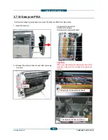
3.7.10 Side joint PBA
1. Open the side unit.
Perform the following procedure to remove the Side jo
2. Release the side joint board cover after removing
2 screws.
Push !
Service Manual
3-4
nt Procedure
3. Unplug all connectors.
4. Remove 4 screws.
5. Release the side joint board.
int PBA from the printer.
j
CAUTION
When you reassemble the side joint board to the
side unit, make sure the harness arrangement is
correct.
The harness on the side joint board.
The harness of Face up Sensor.
SAMSUNG ELECTRONICS
46
Содержание SCX-82x0 series
Страница 13: ...10 2 Abbreviations 10 4 ...
Страница 112: ...2 Product Description SAMSUNG ELECTRONICS Service Manual 2 94 ...
Страница 378: ...8 System 8 1 Engine 1 8 System Diagram 8 1 Engine 1 Service Manual 8 Diagram SAMSUNG ELECTRONICS 1 ...
Страница 379: ...8 System 8 2 Engine 2 8 2 Engine 2 Service Manual 8 Diagram SAMSUNG ELECTRONICS 2 ...
Страница 380: ...8 System 8 3 Engine 3 8 3 Engine 3 Service Manual 8 Diagram SAMSUNG ELECTRONICS 3 ...
Страница 381: ...8 System 8 4 Scan DADF 8 4 Scan DADF Service Manual 8 Diagram SAMSUNG ELECTRONICS 4 ...
Страница 382: ...8 System 8 5 Heater Fuse 8 5 Heater Fuse Service Manual 8 Diagram SAMSUNG ELECTRONICS 5 ...


