4-16
Summary of Product
Samsung Electronics
Service Manual
4.5 Engine F/W
4.5.1 Feeding
If feeding from the cassette the drive of the pickup roller is controlled by controlling the pick-up solenoid. The on/off
of the solenoid is controlled by controlling the general output port or the external output port. If feeding from the
manual feeder the set decides to feed the paper according to the operation of the manual sensor, and by driving
the main motor, insert the paper in front of the feed sensor. When paper moves the occurrence of a paper jam is
judged as below.
4.5.1.1 Jam 0 – Jam in Feed area
• After a page was picked up, paper did not enter the unit due to a paper misfeed.
• After a page was picked up, paper entered but it did not reach the feed sensor in certain time due to slip, etc.
• After a page was picked up, if the feed sensor is not on try to pick up again. After retrying if the feed sensor is still
not on after certain time, it is Jam 0.
- this indicates that the leading edge of the paper doesn't pass the feed sensor within a certain time.
• Even though the paper reaches the feed sensor, the feed sensor does not turn on.
- this indicates that the leading edge of the paper already passed the feed sensor or that the sensor is faulty.
4.5.1.2 Jam 1 – Jam inside the print engine
• After the leading edge of the paper passes the feed sensor, the trailing edge of the paper does not pass the feed
sensor within certain time. (During this time the feed sensor cannot be Off)
• After the leading edge of the paper passes the feed sensor, the paper does not reach the exit sensor within a
certain time. (The exit sensor cannot be On during this time)
- There is already paper between the feed sensor and the exit sensor.
4.5.1.3 Jam 2 – Jam in the Exit area
• After the trailing edge of the paper passes the feed sensor the trailing edge of the paper does not pass the exit
sensor within certain time.
4.5.2 Drive
The main motor drives the paper feed, developing unit and the Fuser It is driven by software which controls the
acceleration, constant speed and deceleration profiles. The Motor is managed with an AN44060 driver IC and
controlled by step and enable signals from the CPU.
4.5.3 Transfer
The charging voltage, developing voltage and the transfer voltage are controlled by PWM (Pulse Width
Modulation). Each output voltage is changeable according to the PWM duty cycle. The transfer voltage used when
the paper passes the transfer roller is decided by environment recognition. The resistance value of the transfer
roller changes due to the surrounding environment in the room or within the set, this change in resistance in turn
changes the value of the voltage due to loading. This voltage is fed back into the set through the A/D converter.
Based on this fed back value the PWM cycle is changed to maintain the required transfer voltage Page 4-10 has a
different chip number Which is correct
Содержание scx-4100 series
Страница 13: ...2 6 Reference Information Samsung Electronics Service Manual 2 4 2 A4 2 Pattern ...
Страница 14: ...2 7 Samsung Electronics Reference Information Service Manual 2 4 3 A4 IDC 5 Patten ...
Страница 15: ...2 8 Reference Information Samsung Electronics Service Manual MEMO ...
Страница 21: ...3 6 Specifications Samsung Electronics Service Manual MEMO ...
Страница 23: ...4 2 Summary of Product Samsung Electronics Service Manual 4 1 2 Rear View ...
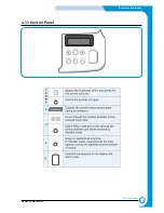
Страница 24: ...4 3 Samsung Electronics Summary of product Service Manual 4 1 3 Control Panel ...
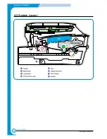
Страница 25: ...4 4 Summary of Product Samsung Electronics Service Manual 4 2 System Layout SCAN PART ...
Страница 39: ...4 18 Summary of Product Samsung Electronics Service Manual MEMO ...
Страница 57: ...5 18 Disassembly and Reassembly Samsung Electronics Service Manual MEMO ...
Страница 93: ...7 28 Troubleshooting Samsung Electronics Service Manual MEMO ...
Страница 110: ...9 9 9 1 Samsung Electronics Block Diagram Service Manual 9 Block Diagram ...


