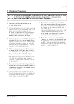
1-3 Servicing Precautions
1. Servicing precautions are printed on the
cabinet. Follow them.
2. Always unplug the unit’s AC power cord from
the AC power source before attempting to: (a)
Remove or reinstall any component or
assembly, (b) Disconnect an electrical plug or
connector, (c) Connect a test component in
parallel with an electrolytic capacitor.
3. Some components are raised above the printed
circuit board for safety. An insulation tube or
tape is sometimes used. The internal wiring is
sometimes clamped to prevent contact with
thermally hot components. Reinstall all such
elements to their original position.
4. After servicing, always check that the screws,
components and wiring have been correctly
reinstalled. Make sure that the portion around
the serviced part has not been damaged.
5. Check the insulation between the blades of the
AC plug and accessible conductive parts
(examples: metal panels, input terminals and
earphone jacks).
6. Never defeat any of the B+ voltage interlocks.
Do not apply AC power to the unit (or any of
its assemblies) unless all solid-state heat sinks
are correctly installed.
7. Always connect a test instrument’s ground
lead to the instrument chassis ground before
connecting the positive lead; always remove
the instrument’s ground lead last.
8. Plasma display panels have partial afterim-
ages when a same picture continues to be dis-
played for a certain time. This happens due to
the degradation of brightness caused by a
scale-down effect.
To prevent such afterimages when displaying
a same picture for a certain time, be sure to
reduce the level of brightness and contrast.
ex) Contrast : 50 or 75, Brightness : 25
9. Plasma display is an array of pixels(cells).
Therefore, if at least 99.9% pixels keep normal,
the appropriate panel is judged as ‘approved
product.’ Even though some of pixels keep
luminescent or always light off, do not worry
because the panel is approved.
Precautions
Samsung Electronics
1-3
Warning 1 : First read the “Safety Precautions” section of this manual. If some unforeseen circumstance creates a
conflict between the servicing and safety precautions, always follow the safety precautions.
Warning 2 : An electrolytic capacitor installed with the wrong polarity might explode.
Содержание PPM42S2X/XAA
Страница 2: ...ELECTRONICS Samsung Electronics Co Ltd APR 2002 Printed in Korea AA82 ...
Страница 10: ...3 2 Samsung Electronics MENO ...
Страница 25: ...Circuit Operation Description Samsung Electronics 5 3 5 1 2 D PDP PS 42 BLOCK DIAGRAM ...
Страница 38: ...Circuit Operation Description 5 16 Samsung Electronics 5 2 3 D DRIVER CIRCUIT DIAGRAM ...
Страница 39: ...Circuit Operation Description Samsung Electronics 5 17 5 2 3 E DRIVER BOARD CONNECTOR LAYOUT ...
Страница 40: ...Circuit Operation Description 5 18 Samsung Electronics ...
Страница 41: ...Circuit Operation Description Samsung Electronics 5 19 ...
Страница 42: ...Circuit Operation Description 5 20 Samsung Electronics ...
Страница 43: ...Circuit Operation Description Samsung Electronics 5 21 ...
Страница 44: ...Circuit Operation Description 5 22 Samsung Electronics ...
Страница 45: ...Circuit Operation Description Samsung Electronics 5 23 ...
Страница 46: ...Circuit Operation Description 5 24 Samsung Electronics ...
Страница 47: ...Circuit Operation Description Samsung Electronics 5 25 ...
Страница 48: ...Circuit Operation Description 5 26 Samsung Electronics ...
Страница 49: ...Circuit Operation Description Samsung Electronics 5 27 ...
Страница 50: ...Circuit Operation Description 5 28 Samsung Electronics ...
Страница 51: ...Circuit Operation Description Samsung Electronics 5 29 ...
Страница 52: ...Circuit Operation Description 5 30 Samsung Electronics ...
Страница 53: ...Circuit Operation Description Samsung Electronics 5 31 5 3 Logic part 5 3 1 Logic Board Block diagram ...
Страница 76: ...Circuit Operation Description 5 54 Samsung Electronics 29 Jig board U1 LE01 pin35 30 Jig board U1 LE01 pin46 ...
Страница 77: ...Circuit Operation Description Samsung Electronics 5 55 31 Jig board U2 LE02 pin35 32 Jig board U2 LE02 pin46 ...
Страница 82: ...Circuit Operation Description 5 60 Samsung Electronics ...
Страница 83: ...Circuit Operation Description Samsung Electronics 5 61 ...
Страница 84: ...Circuit Operation Description 5 62 Samsung Electronics MEMO ...
Страница 93: ...Exploded View Parts List Samsung Electronics 7 1 7 Exploded View Parts List 7 1 PPM42S2X XAA ...
Страница 106: ...Electrical Parts List 8 12 Samsung Electronics MEMO ...
Страница 128: ...10 14 Samsung Electronics MEMO ...
Страница 130: ...11 2 Samsung Electronics MENO ...
Страница 133: ...Samsung Electronics Schematic Diagrams 12 3 TP01 12 3 SCALER3 3D COMB FILTER TP01 CVBS IN ...
Страница 134: ...Schematic Diagrams 12 4 Samsung Electronics 12 4 SCALER4 VIDEO DECODER PIP FIRST IN OUTPUT ...
Страница 135: ...Samsung Electronics Schematic Diagrams 12 5 12 5 SCALER5 VIDEO DA CON ...
Страница 137: ...Samsung Electronics Schematic Diagrams 12 7 12 7 SCALER7 ADC VIDEO TP20 TP21 TP19 TP19 HS OUT TP20 VHS TP21 VCLK ...
Страница 138: ...Schematic Diagrams 12 8 Samsung Electronics 12 8 SCALER8 ADC PC TP23 TP24 TP22 TP22 MHSYNC TP23 MHS TP24 PCLK ...
Страница 140: ...Schematic Diagrams 12 10 Samsung Electronics 12 10 SCALER10 POWER DEGUGER MEMORY REMOCON RS232 RTC ...
Страница 141: ...Samsung Electronics Schematic Diagrams 12 11 12 11 SOUND ...
Страница 143: ...Samsung Electronics Schematic Diagrams 12 13 12 13 CONTROL REMOCON CONTROL REMOCON ...


