Handling Description
Samsung Electronics
9-5
9-2 Wall Mount
9-2-1 Notice for installing
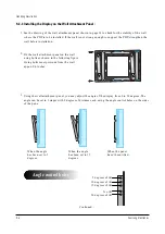
1. Do not install the PDP in any location other than vertical walls.
2. To protect the performance of the PDP and prevent problems, avoid the following places.
l
Do not install next to smoke and fire detectors.
l
Do not install in an area subjected to vibration.
l
Do not install in an area subjected to high voltage.
l
Do not install near or around any heating apparatus.
3. Use only recommended parts and components
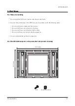
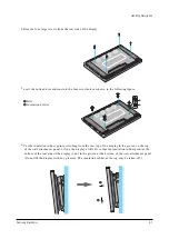
9-2-2 Parts (Wall attachment panel is sold separately. Check with your dealer or Samsung)
Insulation holder
bolt
34.61 inches
24.57 inches
Содержание PPM42S2X/XAA
Страница 2: ...ELECTRONICS Samsung Electronics Co Ltd APR 2002 Printed in Korea AA82 ...
Страница 10: ...3 2 Samsung Electronics MENO ...
Страница 25: ...Circuit Operation Description Samsung Electronics 5 3 5 1 2 D PDP PS 42 BLOCK DIAGRAM ...
Страница 38: ...Circuit Operation Description 5 16 Samsung Electronics 5 2 3 D DRIVER CIRCUIT DIAGRAM ...
Страница 39: ...Circuit Operation Description Samsung Electronics 5 17 5 2 3 E DRIVER BOARD CONNECTOR LAYOUT ...
Страница 40: ...Circuit Operation Description 5 18 Samsung Electronics ...
Страница 41: ...Circuit Operation Description Samsung Electronics 5 19 ...
Страница 42: ...Circuit Operation Description 5 20 Samsung Electronics ...
Страница 43: ...Circuit Operation Description Samsung Electronics 5 21 ...
Страница 44: ...Circuit Operation Description 5 22 Samsung Electronics ...
Страница 45: ...Circuit Operation Description Samsung Electronics 5 23 ...
Страница 46: ...Circuit Operation Description 5 24 Samsung Electronics ...
Страница 47: ...Circuit Operation Description Samsung Electronics 5 25 ...
Страница 48: ...Circuit Operation Description 5 26 Samsung Electronics ...
Страница 49: ...Circuit Operation Description Samsung Electronics 5 27 ...
Страница 50: ...Circuit Operation Description 5 28 Samsung Electronics ...
Страница 51: ...Circuit Operation Description Samsung Electronics 5 29 ...
Страница 52: ...Circuit Operation Description 5 30 Samsung Electronics ...
Страница 53: ...Circuit Operation Description Samsung Electronics 5 31 5 3 Logic part 5 3 1 Logic Board Block diagram ...
Страница 76: ...Circuit Operation Description 5 54 Samsung Electronics 29 Jig board U1 LE01 pin35 30 Jig board U1 LE01 pin46 ...
Страница 77: ...Circuit Operation Description Samsung Electronics 5 55 31 Jig board U2 LE02 pin35 32 Jig board U2 LE02 pin46 ...
Страница 82: ...Circuit Operation Description 5 60 Samsung Electronics ...
Страница 83: ...Circuit Operation Description Samsung Electronics 5 61 ...
Страница 84: ...Circuit Operation Description 5 62 Samsung Electronics MEMO ...
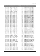
Страница 93: ...Exploded View Parts List Samsung Electronics 7 1 7 Exploded View Parts List 7 1 PPM42S2X XAA ...
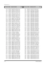
Страница 106: ...Electrical Parts List 8 12 Samsung Electronics MEMO ...
Страница 128: ...10 14 Samsung Electronics MEMO ...
Страница 130: ...11 2 Samsung Electronics MENO ...
Страница 133: ...Samsung Electronics Schematic Diagrams 12 3 TP01 12 3 SCALER3 3D COMB FILTER TP01 CVBS IN ...
Страница 134: ...Schematic Diagrams 12 4 Samsung Electronics 12 4 SCALER4 VIDEO DECODER PIP FIRST IN OUTPUT ...
Страница 135: ...Samsung Electronics Schematic Diagrams 12 5 12 5 SCALER5 VIDEO DA CON ...
Страница 137: ...Samsung Electronics Schematic Diagrams 12 7 12 7 SCALER7 ADC VIDEO TP20 TP21 TP19 TP19 HS OUT TP20 VHS TP21 VCLK ...
Страница 138: ...Schematic Diagrams 12 8 Samsung Electronics 12 8 SCALER8 ADC PC TP23 TP24 TP22 TP22 MHSYNC TP23 MHS TP24 PCLK ...
Страница 140: ...Schematic Diagrams 12 10 Samsung Electronics 12 10 SCALER10 POWER DEGUGER MEMORY REMOCON RS232 RTC ...
Страница 141: ...Samsung Electronics Schematic Diagrams 12 11 12 11 SOUND ...
Страница 143: ...Samsung Electronics Schematic Diagrams 12 13 12 13 CONTROL REMOCON CONTROL REMOCON ...

